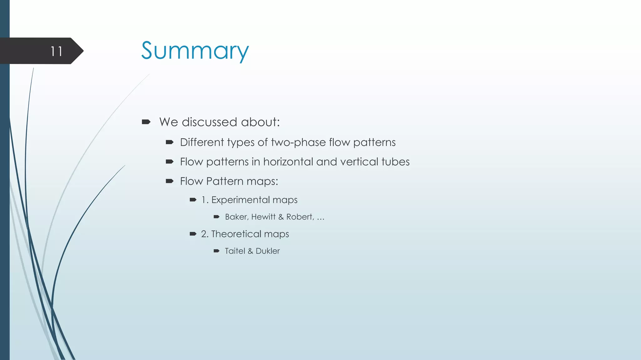
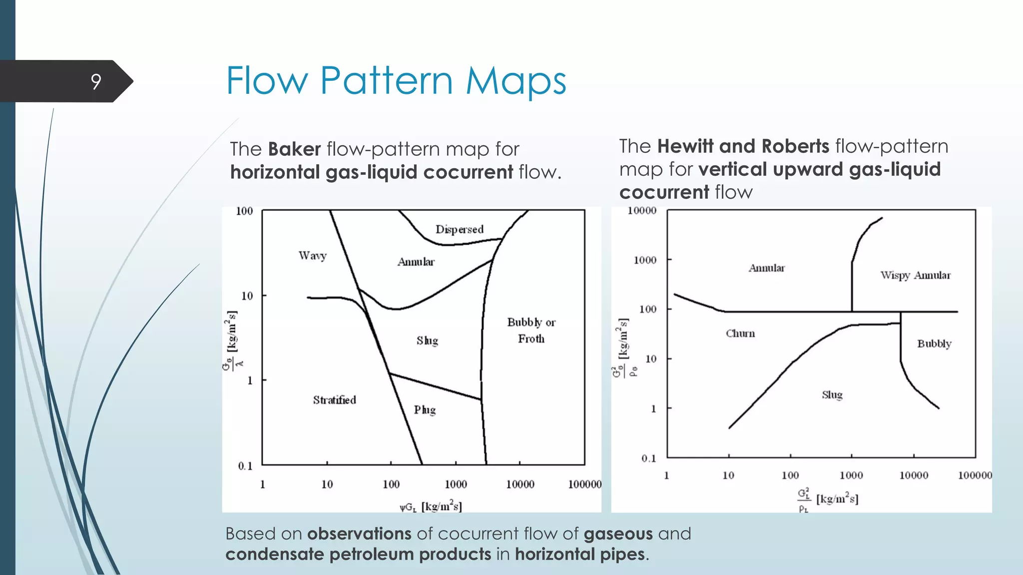
This document discusses two-phase flow patterns and flow pattern maps. It describes different flow patterns that can occur in horizontal and vertical tubes, including stratified, wavy, plug, dispersed bubble, slug and annular flows. Flow pattern maps are used to predict the flow patterns based on gas and liquid velocities. Empirical maps are developed based on experiments, while theoretical maps are developed using models. Examples of both empirical maps, like those by Baker and Hewitt & Roberts, and theoretical maps, like by Taitel & Dukler, are provided and compared.
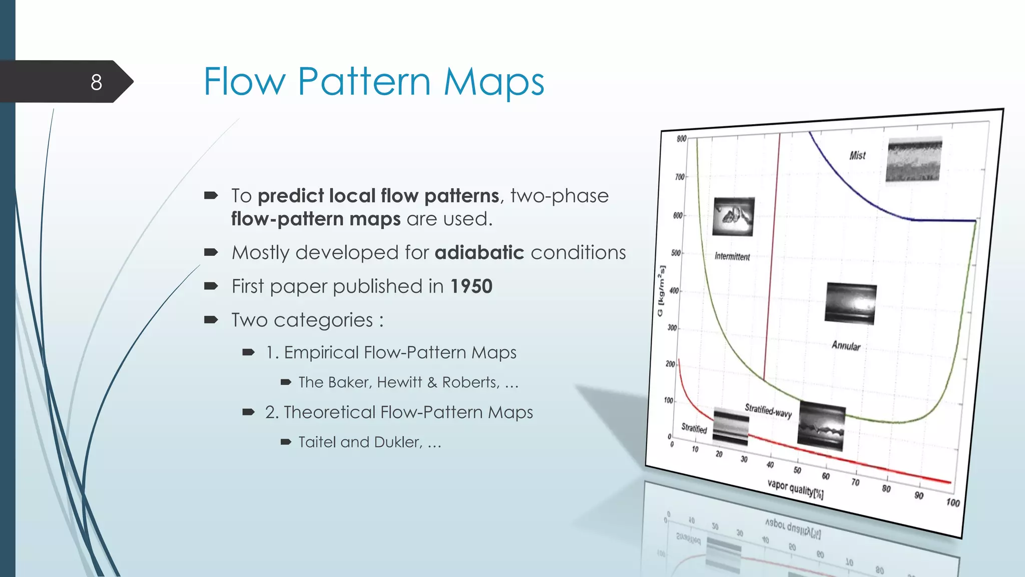
![Flow Pattern Maps
The Theoretical Taitel and Dukler flow-
pattern map for horizontal gas-liquid
cocurrent flow :
The Kattan–Thome–Favrat flow-
pattern map compared to the
Steiner map :
10
Evaluated for R410A at Tsat=5°C in a 13.84 mm
internal diameter tube at different heat fluxes
X : Martinelli parameter
X= [(dP/dZ)L / (dP/dZ)G]^0.5](https://image.slidesharecdn.com/seminar1-140505091806-phpapp01/75/Two-Phase-Flow-Patterns-and-Flow-Pattern-Maps-10-2048.jpg)