KONGUNADU COLLEGE OF ENGINEERING
AND TECHNOLOGY
(AUTONOMOUS)
WELCOME YOU ALL!!!
Department of Information Technology
SUBJECT NAME:
STRUCTURED PROGRAMMING USING C
• Why to Choose ECE? And what is the scope in ECE?
• Why this paper for Electronics and Communication Engineering
in first semester?
SYLLABUS:
TEXT BOOK DETAILS:
INTRODUCTION
COMPUTER:
• A Computer is an electronic machine that accepts data from the
user, processes the data by performing calculations and
operations on it, and generates the desired output results.
• Computer performs both simple and complex operations, with
speed and accuracy.
DIGITAL AND ANALOG COMPUTERS:
• A digital computer uses distinct values to represent the data
internally. All information are represented using the digits 0s
and 1s.
• Example: Personal computers
• Analog computer is another kind of a computer that represents
data as variable across a continuous range of values.
• Example: Temperature, Pressure and voltage.
CHARACTERISTICS OF COMPUTER:
• Speed
• Accuracy
• Diligence
• Storage capacity
• Versatility
COMPONENTS OF COMPUTER HARDWARE:
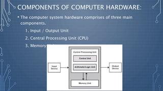
• The computer system hardware comprises of three main
components.
1. Input / Output Unit
2. Central Processing Unit (CPU)
3. Memory Unit
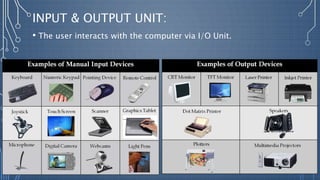
INPUT & OUTPUT UNIT:
• The user interacts with the computer via I/O Unit.
CENTRAL PROCESSING UNIT:
• Arithmetic Logic Unit (ALU)
• Control Unit (CU)
• Registers
ARITHMETIC & LOGIC UNIT:
• ALU Consist of two units-Arithmetic unit and Logical unit.
• Arithmetic unit performs arithmetic operations on the data.
Like Addition, Subtraction, Multiplication and Division.
• The logic unit of ALU is responsible for performing logical
operations. Logical unit performs comparisons of numbers,
letters and special characters.
• Logical operations include testing for greater than, less than or
equal to condition.
CONTROL UNIT:
• It organizes the processing of data and instructions. It acts as a
supervisor. It controls and coordinates the activity of the other
unit of computer.
REGISTERS:
• Registers are high speed storage areas within the CPU, but have
the least storage capacity.
• Registers are not referred by their address, but are directly
accessed and manipulated by the CPU during instruction
execution.
• Registers store data, instructions, addresses and intermediate
results of processing. Registers are often referred to as the
CPU’s Corking Memory.
REGISTERS: (CONTD.,)
• Program Counter (PC) – Contains the address of next instruction to
be processed.
• Instruction Register (IR) – Contains the current Instruction most
recently fetched.
• Memory Address Register (MAR) – Contains the address of next
location in the memory to be accessed.
• Accumulator (ACC) – Stores the result of AL operations.
• Memory Buffer Register (MBR) – Temporarily stores data from
memory or the data to be sent to memory.
• Data Register (DR) – Stores the operands and any other data.
MEMORY UNIT:
• Used for storage purpose
• Two Types:
1. Primary Memory
2. Secondary Memory
3. Cache Memory
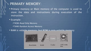
PRIMARY MEMORY:
• Primary memory or Main memory of the computer is used to
store the data and instructions during execution of the
instruction.
• Example:
ROM-Read Only Memory
RAM-Random Access Memory
• RAM is volatile memory, but ROM is non-volatile memory
SECONDARY MEMORY:
• The secondary storage stores data and instructions
permanently.
• The information can stored in secondary memory for a long
time (Years), and is generally permanently in nature unless
erased by the user.
• It is Non-volatile memory.
• It provides backup storage for data and instructions.
• Examples- Hard disk drives, floppy drive and optical disk
drives.
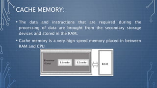
CACHE MEMORY:
• The data and instructions that are required during the
processing of data are brought from the secondary storage
devices and stored in the RAM.
• Cache memory is a very hign speed memory placed in between
RAM and CPU
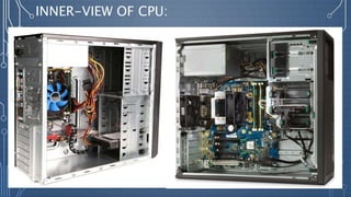
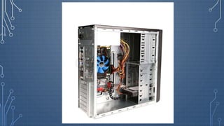
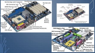
INNER-VIEW OF CPU:
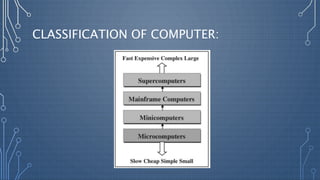
CLASSIFICATION OF COMPUTER:
HISTORY OF COMPUTER
• The key development that took place till the first computer was
developed are as follows:
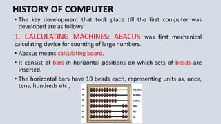
1. CALCULATING MACHINES: ABACUS was first mechanical
calculating device for counting of large numbers.
• Abacus means calculating board.
• It consist of bars in horizontal positions on which sets of beads are
inserted.
• The horizontal bars have 10 beads each, representing units as, once,
tens, hundreds etc.,
2. NEPIAR’S BONES:
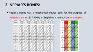
• Nepier’s Bones was a mechanical device built for the purpose of
multiplication in 1617 AD by an English mathematician John Napier.
3. SLIDE RULE:
• Slide rule was developed by an English Mathematician Edmund
Gunter in the 16th century.
• Using the slide rule, one could perform operations like addition,
subtraction, multiplication and division.
• It was used extensively till late 1970s.
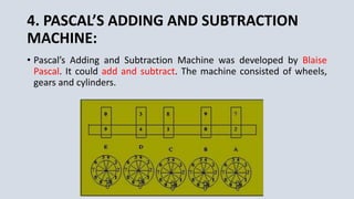
4. PASCAL’S ADDING AND SUBTRACTION
MACHINE:
• Pascal’s Adding and Subtraction Machine was developed by Blaise
Pascal. It could add and subtract. The machine consisted of wheels,
gears and cylinders.
5.LEIBNIZ’S MULTIPLICATION AND DIVIDING
MACHINE:
• Leibniz’s Multiplication and Dividing Machine was a mechanical
device that could both multiply and divide.
• The German Philosopher and mathematician Gottfried Leibniz built it
around 1973.
6. PUNCH CARD SYSTEM
• Punch Card System was developed by Jacquard to control the power
loom in 1801.
• He Invented the punched card reader that could recognize the
presence of hole in the punched card as binary one and absence of
the hole as binary zero.
• The 0’s and 1’s are the basis of the modern digital computer.
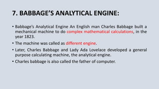
7. BABBAGE’S ANALYTICAL ENGINE:
• Babbage’s Analytical Engine An English man Charles Babbage built a
mechanical machine to do complex mathematical calculations, in the
year 1823.
• The machine was called as different engine.
• Later, Charles Babbage and Lady Ada Lovelace developed a general
purpose calculating machine, the analytical engine.
• Charles babbage is also called the father of computer.
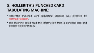
8. HOLLERITH’S PUNCHED CARD
TABULATING MACHINE:
• Hollerith’s Punched Card Tabulating Machine was invented by
Herman Hollerith.
• The machine could read the information from a punched card and
process it electronically.
GENERATION OF COMPUTERS
• The Generation of computers in terms of,
1. The Technology used by them(Hardware and Software)
2. Computing Characteristics (Speed, i.e Number of instructions
executed per second)
3. Physical appearance
4. Their applications.
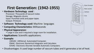
First Generation: (1942-1955)
• Hardware Technology used :
Processor: Thousands of vacuum tubes
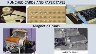
Storage: Magnetic drums
Input: Punched cards and paper tapes
Output: Printouts
• Software Technology used: Machine languages
• Computing Characteristics: Milliseconds
• Physical Appearance:
Large in size and it required a large room for installation.
• Applications: Scientific applications.
• Example:
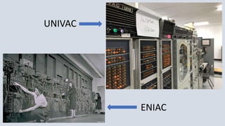
UNIVAC- UNIVersal Automated Computer.
ENIAC- Electronic Numerical Integrator and Calculator.
EDVAC- Electronic Discrete Variable Automatic Computers.
• Disadvantages: It used large number of vaccum tubes and it generates a lot of heat.
PUNCHED CARDS AND PAPER TAPES
Magnetic Drums
UNIVAC
ENIAC
Second Generation: (1955-1964)
• Hardware Technology used : Transistors used
Magnetic cores Technology were used for main memory
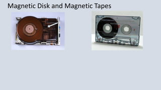
Magnetic Disk and Tapes as secondary storage media.
• Software technology used: Assembly languages
• High level Programming languages such as early versions COBOL and FORTRAN were
developed in this period.
• Computing Characteristics: Micro seconds.
• Physical Appearance: Transistors are small in size. So, the size of computer is
also reduced.
• Example: Honeywell400, IBM 7030, CDC 1604
• Disadvantages:
 Air-conditioning required.
 Frequent maintenance required.
 Manual assembly of individual components into a functioning unit was required.
 Commercial production was difficult and costly.
Magnetic Disk and Magnetic Tapes
Third Generation: (1964-1975)
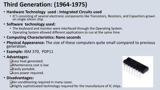
• Hardware Technology used : Integrated Circuits used
• IC’s consisting of several electronic components like Transistors, Resistors, and Capacitors grown
on single silicon chip.
• Software technology used:
• The keyboard and monitor were interfaced through the Operating System.
• Operating System allowed different applications to run at the same time.
• Computing Characteristics: Nano seconds
• Physical Appearance: The size of these computers quite small compared to previous
generation.
• Example: IBM 370, PDP11
• Advantages:
Less heat generated.
Maintenance cost is low
Easily portable.
Less power required.
• Disadvantages:
Air-conditioning required in many cases.
Highly sophisticated technology required for the manufacture of IC chips.
Fourth Generation: (1975-1989)
• Hardware Technology: Microprocessor used
• Depends on integrated circuit but uses microprocessor.
• MP is built onto a single piece of silicon known as chip. It is 0.5cm long and not more than 0.05cm thick.
• Fourth generation led to LSI [large scale integration] and VLSI [very large scale integration].
• Magnetic core memories were substituted by semi conductor memories.
• Hard disk becomes economical, smaller and large capacity.
• Software technology used:
• Several New operating system like MS-DOS and MS-Windows were developed.
• This generation Supports Graphical User Interface (GUI)
• GUI is a user friendly interface that allows user to interact with the computer via menus and icons.
• Computing Characteristics: Pico seconds
• Physical Appearance: The size is very small compared to previous generation.
• Example: IBM PC, APPLE II, VAX 9000, CRAY-1,2,X
• Advantages: Smallest in size, Very reliable, Heat generated is negligible, No air conditioning required in most
cases, Hardware failure is negligible easily portable because of their small size, Cheapest among all
generations.
• Disadvantages: Highly sophisticated technology required for the manufacture of LSI chips.
Fifth Generation: (1989 to present)
• Hardware Technology: Artificial Intelligence used
ICs with ULSI (Ultra Large Scale Integration)
Large Capacity main memory and hard disks.
Optical disks as portable read only storage media
very powerful mainframe.
• Software technology used:
The information is become readily available to computer users through World Wide
Web(WWW).
Multimedia applications
internet based applications like e-mail.
• Three characteristics of 5th generation computer are
Mega chips
Parallel processing
Artificial Intelligence [AI]
• Advantages:
This generation computers are very fast, highly reliable, user friendly systems.
Having much faster and large primary storage capacity.
Support parallel programming
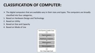
CLASSIFICATION OF COMPUTER:
 The digital computers that are available vary in their sizes and types. The computers are broadly
classified into four categories,
1. Based on Hardware Design and Technology
2. Based on Utility
3. Based on Size and Capacity
4. Based on Mode of Use
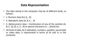
Data Representation
• The data stored in the computer may be of different kinds, as
follows:
• 1. Numeric data (0,1,2,…9)
• 2. Alphabetic data (A, B, C…. Z)
• 3. Alphanumeric data – Combination of any of the symbols (A,
B, C…Z), (0, 1, 2….9) or special characters (+, -, blank) etc.
• All kinds of data, be it alphabets, numbers, symbols, sound data
or video data, is represented in terms of 0s and 1s in the
computer.
Number System
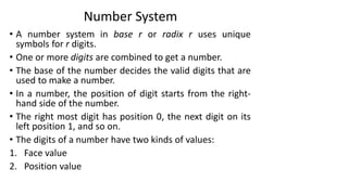
• A number system in base r or radix r uses unique
symbols for r digits.
• One or more digits are combined to get a number.
• The base of the number decides the valid digits that are
used to make a number.
• In a number, the position of digit starts from the right-
hand side of the number.
• The right most digit has position 0, the next digit on its
left position 1, and so on.
• The digits of a number have two kinds of values:
1. Face value
2. Position value
Number System
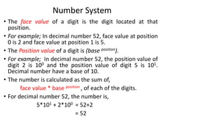
• The face value of a digit is the digit located at that
position.
• For example; In decimal number 52, face value at position
0 is 2 and face value at position 1 is 5.
• The Position value of a digit is (base position).
• For example; In decimal number 52, the position value of
digit 2 is 100 and the position value of digit 5 is 101.
Decimal number have a base of 10.
• The number is calculated as the sum of,
face value * base position , of each of the digits.
• For decimal number 52, the number is,
5*101 + 2*100 = 52+2
= 52
Number System
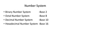
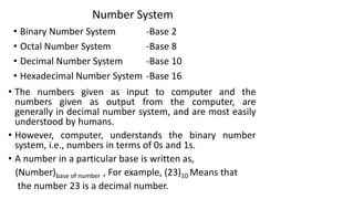
• Binary Number System -Base 2
• Octal Number System -Base 8
• Decimal Number System -Base 10
• Hexadecimal Number System -Base 16
Number System
• Binary Number System -Base 2
• Octal Number System -Base 8
• Decimal Number System -Base 10
• Hexadecimal Number System -Base 16
• The numbers given as input to computer and the
numbers given as output from the computer, are
generally in decimal number system, and are most easily
understood by humans.
• However, computer, understands the binary number
system, i.e., numbers in terms of 0s and 1s.
• A number in a particular base is written as,
(Number)base of number , For example, (23)10 Means that
the number 23 is a decimal number.
Decimal Number System
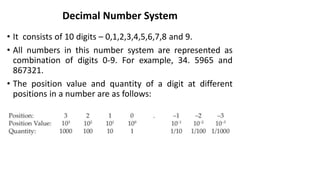
• It consists of 10 digits – 0,1,2,3,4,5,6,7,8 and 9.
• All numbers in this number system are represented as
combination of digits 0-9. For example, 34. 5965 and
867321.
• The position value and quantity of a digit at different
positions in a number are as follows:
Binary Number System
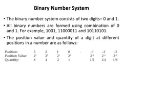
• The binary number system consists of two digits– 0 and 1.
• All binary numbers are formed using combination of 0
and 1. For example, 1001, 11000011 and 10110101.
• The position value and quantity of a digit at different
positions in a number are as follows:
Octal Number System
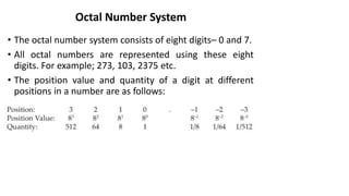
• The octal number system consists of eight digits– 0 and 7.
• All octal numbers are represented using these eight
digits. For example; 273, 103, 2375 etc.
• The position value and quantity of a digit at different
positions in a number are as follows:
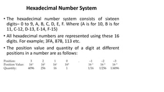
Hexadecimal Number System
• The hexadecimal number system consists of sixteen
digits– 0 to 9, A, B, C, D, E, F. Where (A is for 10, B is for
11, C-12, D-13, E-14, F-15)
• All hexadecimal numbers are represented using these 16
digits. For example; 3FA, 87B, 113 etc.
• The position value and quantity of a digit at different
positions in a number are as follows:
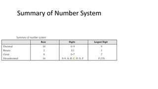
Summary of Number System
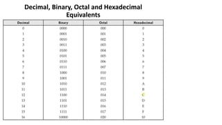
Decimal, Binary, Octal and Hexadecimal
Equivalents
Conversions
• Conversion from Decimal to Binary, Octal, Hexadecimal
• Conversion of Binary, Octal, Hexadecimal to Decimal
• Conversion of Binary to Octal, Hexadecimal
• Conversion of Octal, Hexadecimal to Binary
Conversion from Decimal to Binary, Octal,
Hexadecimal
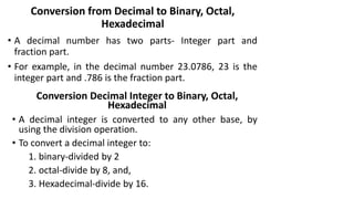
• A decimal number has two parts- Integer part and
fraction part.
• For example, in the decimal number 23.0786, 23 is the
integer part and .786 is the fraction part.
Conversion Decimal Integer to Binary, Octal,
Hexadecimal
• A decimal integer is converted to any other base, by
using the division operation.
• To convert a decimal integer to:
1. binary-divided by 2
2. octal-divide by 8, and,
3. Hexadecimal-divide by 16.
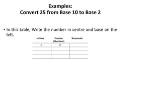
Examples:
Convert 25 from Base 10 to Base 2
• In this table, Write the number in centre and base on the
left.
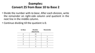
Examples:
Convert 25 from Base 10 to Base 2
• Divide the number with to base. After each division, write
the remainder on right-side column and quotient in the
next line in the middle column.
• Continue dividing till the quotient is 0.
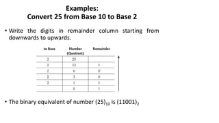
Examples:
Convert 25 from Base 10 to Base 2
• Write the digits in remainder column starting from
downwards to upwards.
• The binary equivalent of number (25)10 is (11001)2
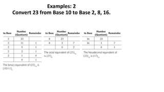
Examples: 2
Convert 23 from Base 10 to Base 2, 8, 16.
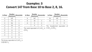
Examples: 3
Convert 147 from Base 10 to Base 2, 8, 16.
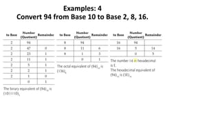
Examples: 4
Convert 94 from Base 10 to Base 2, 8, 16.
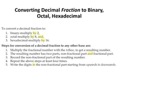
Converting Decimal Fraction to Binary,
Octal, Hexadecimal
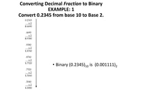
• Fractional number is a number less than 1. it may be .5,
.00453, .564, etc.
• We use multiplication operation to convert decimal
fraction to any other base.
Converting Decimal Fraction to Binary
EXAMPLE: 1
Convert 0.2345 from base 10 to Base 2.
• Binary (0.2345)10 is (0.001111)2
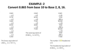
Converting Decimal Fraction to Binary,
Octal, Hexadecimal
EXAMPLE: 2
Convert 0.865 from base 10 to Base 2, 8, 16.
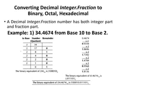
Converting Decimal Integer.Fraction to
Binary, Octal, Hexadecimal
• A Decimal Integer.Fraction number has both integer part
and fraction part.
Example: 1) 34.4674 from Base 10 to Base 2.
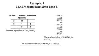
Example: 2
34.4674 from Base 10 to Base 8.
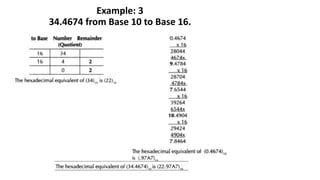
Example: 3
34.4674 from Base 10 to Base 16.
Conversion of Binary, Octal, Hexadecimal to
Decimal
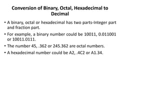
• A binary, octal or hexadecimal has two parts-Integer part
and fraction part.
• For example, a binary number could be 10011, 0.011001
or 10011.0111.
• The number 45, .362 or 245.362 are octal numbers.
• A hexadecimal number could be A2, .4C2 or A1.34.
Conversion of Binary, Octal, Hexadecimal to
Decimal
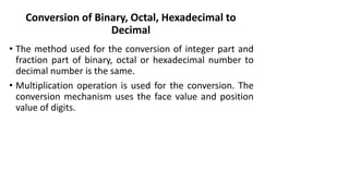
• The method used for the conversion of integer part and
fraction part of binary, octal or hexadecimal number to
decimal number is the same.
• Multiplication operation is used for the conversion. The
conversion mechanism uses the face value and position
value of digits.
Conversion of Binary, Octal, Hexadecimal to
Decimal
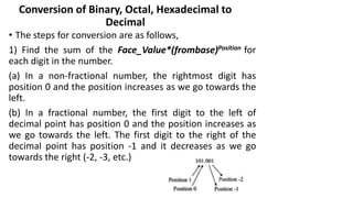
• The steps for conversion are as follows,
1) Find the sum of the Face_Value*(frombase)Position for
each digit in the number.
(a) In a non-fractional number, the rightmost digit has
position 0 and the position increases as we go towards the
left.
(b) In a fractional number, the first digit to the left of
decimal point has position 0 and the position increases as
we go towards the left. The first digit to the right of the
decimal point has position -1 and it decreases as we go
towards the right (-2, -3, etc.)
Conversion of Binary, Octal, Hexadecimal to
Decimal
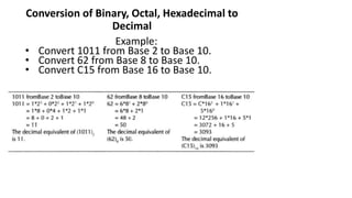
Example:
• Convert 1011 from Base 2 to Base 10.
• Convert 62 from Base 8 to Base 10.
• Convert C15 from Base 16 to Base 10.
Conversion of Binary, Octal, Hexadecimal to
Decimal
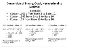
Example:
• Convert .1011 from Base 2 to Base 10.
• Convert .345 from Base 8 to Base 10.
• Convert .15 from Base 16 to Base 10.
Conversion of Binary, Octal, Hexadecimal to
Decimal
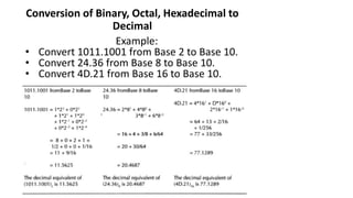
Example:
• Convert 1011.1001 from Base 2 to Base 10.
• Convert 24.36 from Base 8 to Base 10.
• Convert 4D.21 from Base 16 to Base 10.
Conversion of Binary to Octal & Hexadecimal
• A binary number can be converted into octal or
hexadecimal number using a shortcut method. The
shortcut method is based on the flowing information,
• An octal from 0 to 7 can be represented as a combination
of 3 bits, since 23 =8.
• A hexadecimal digit from 0 to 15 can be represented as a
combination of 4 bits, since 24=16.
Conversion of Binary to Octal & Hexadecimal
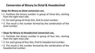
Steps for Binary to Octal conversion are,
• 1. Partition the binary number in group of three bits, starting
from the right most side.
• 2. For each group of three bits, find its octal number.
• 3. The result is the number formed by the combination of the
octal number.
• Steps for Binary to Hexadecimal conversion are,
• 1. Partition the binary number in group of four bits, starting
from the right most side.
• 2. For each group of four bits, find its hexadecimal number.
• 3. The result is the number formed by the combination of the
hexadecimal number.
Conversion of Binary to Octal & Hexadecimal
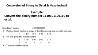
Example:
Convert the binary number 1110101100110 to
octal.
Conversion of Binary to Octal & Hexadecimal
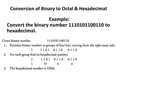
Example:
Convert the binary number 1110101100110 to
hexadecimal.
Conversion of Octal & Hexadecimal to Binary
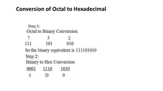
Conversion of Octal to Hexadecimal
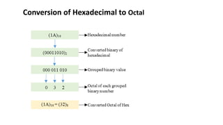
Conversion of Hexadecimal to Octal
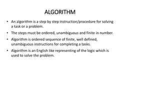
ALGORITHM
• An algorithm is a step by step instruction/procedure for solving
a task or a problem.
• The steps must be ordered, unambiguous and finite in number.
• Algorithm is ordered sequence of finite, well defined,
unambiguous instructions for completing a tasks.
• Algorithm is an English like representing of the logic which is
used to solve the problem.
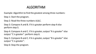
ALGORITHM
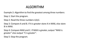
Example: Algorithm to find the greatest among three numbers:
Step 1: Start the program.
Step 2: Read the three numbers A,B,C.
Step 3: Compare A and B. If A is greater perform step 4 else
perform step 5.
Step 4: Compare A and C. If A is greater, output “A is greater” else
output “C is greater”. perform step 6.
Step 5: Compare B and C. If A is greater, output “B is greater” else
output “C is greater”.
Step 6: Stop the program.
ALGORITHM
Example 2: Algorithm to find the greatest among three numbers:
Step 1: Start the program.
Step 2: Read the three numbers A,B,C.
Step 3: Compare A and B. If A is greater store A in MAX, else store
B in MAX.
Step 4: Compare MAX and C. If MAX is greater, output “MAX is
greater” else output “C is greater”.
Step 5: Stop the program.
CONTROL STRUCTURE
• The logic of the program may not always be a linear sequence
of statements to be executed in that order.
• The logic of the program may require execution of statement
based on a decision.
• It may repetitively execute a set of statements unless some
condition is met.
• Control Structures specify the statements to be executed and
the order of execution of statements.
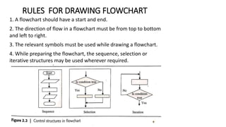
• Sequential
• Selection (Branching or conditional)
• Iteration (loop)
CONTROL STRUCTURE
• Sequential – Instructions are executed in linear order
• Selection (Branching or conditional) – It asks a true/false
question and then selects the next instruction based on the
answer.
• Iteration (loop) – It repeats the execution of a block of
instructions.
FLOWCHART
• Flowchart is a diagrammatic representation of the logic for
solving a task.
• A flowchart is drawn using boxes of different shapes with lines
connecting them to show the flow of control.
• The purpose of drawing flowchart is to make the logic of the
program clearer in a visual form.
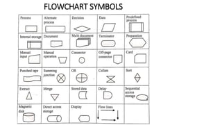
FLOWCHART SYMBOLS
• A flowchart is drawn using different kinds of symbols.
• A symbol used in a flowchart is for a specific purpose.
• The flowchart symbols are available in most word processors
including MS-WORD.
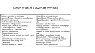
FLOWCHART SYMBOLS
Description of Flowchart symbols
PREPARING FLOWCHART
• A flowchart may be simple or complex.
• The most common symbols that are used to draw a flowchart
are- Process, Decision, Data, Terminator, Connector and flow
lines.
RULES FOR DRAWING FLOWCHART
1. A flowchart should have a start and end.
2. The direction of flow in a flowchart must be from top to bottom
and left to right.
3. The relevant symbols must be used while drawing a flowchart.
4. While preparing the flowchart, the sequence, selection or
iterative structures may be used wherever required.
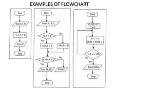
EXAMPLES OF FLOWCHART
PSEUDO CODE
• Pseudo Code is a short hand way of representing a program.
• Pseudo code consists of short, readable and formally styled
English language used for explaining an algorithm.
• Pseudo code does not include details like variable declarations,
subroutines etc.
• Using pseudo code, it is easier for a programmer or non-
programmer to understand the general working of the
program, since it is not based on any programming language.
• Pseudo code cannot be compiled or executed.
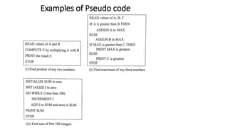
Preparing a Pseudo Code
• Pseudocode is written using structured English.
• In a pseudo code, some terms are commonly used to represent
the various actions.
• For example, For inputting data the terms may be (INPUT, GET,
READ), For outputting data (OUTPUT, PRINT, DISPLAY) For
calculations (COMPUTE, CALCULATE) For incrementing
(INCREMENT), in addition to words like ADD, SUBTRACT,
INITIALIZE used for addition, subtraction and initialization
respectively.
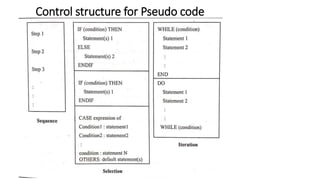
• The control structures- Sequence, Selection and iteration are
used while writing the pseudo code.
Control structure for Pseudo code
Examples of Pseudo code
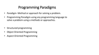
Programming Paradigms
• Paradigm- Method or approach for solving a problem.
• Programming Paradigm-using any programming language to
solve a problem using a methods or approaches.
• Structured programming
• Object Oriented Programming
• Aspect Oriented Programming