It's a P-channel MOSFET. It's job is to act as a "dropless" diode.
The principle is this:
- MOSFETs have a built-in diode across them in reverse bias (an effect of the chemistry)
- The P-channel MOSFET is connected backwards in series with the incoming USB power.
- The internal diode conducts power when there is +5V in to the USB to give power to the board.
- The diode imposes a voltage drop, but there is enough voltage still to run the circuitry.
- An op-amp compares the incoming voltage from the barrel jack (divided by 2) against 3.3V. If it's less than 3.3V (6.6V incoming) or not there at all, it turns on the P-channel MOSFET
- The MOSFET then short circuits the internal diode removing the voltage drop, giving the full 5V from the USB to the rest of the board.
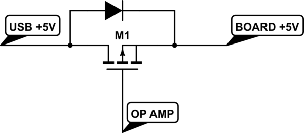
simulate this circuit – Schematic created using CircuitLab
Note: diode shown is internal to the MOSFET.
The MOSFET is designated T2 in the schematic, and is a FDN340P on the reference design, although the actual model is not that critical, as long as the threshold voltage is above about -3V and it can happily handle 500mA or more.
