
Abstract
The Coulomb barrier is a classic introductory physics concept and one that is key to understanding nuclear fusion. Yet the idea that fusing nuclei within a single system could exhibit both far-range repulsion and short-range attraction can result in significant cognitive dissonance in students. There are no classical examples of this behaviour and no commercially available demonstration kits. The magnetic ‘Coulomb’ barrier allows a visual and tactile demonstration of the central challenge of nuclear fusion: overcoming the electrostatic forces inherent in the Coulomb barrier. Students directly determine the kinetic energy required to overcome the magnetic potential energy barrier. The Magnetic ‘Coulomb’ Barrier won first place at the 2023 American Academy of Physics Teacher Apparatus Competition in Sacramento, California, USA.

Original content from this work may be used under the terms of the Creative Commons Attribution 4.0 license. Any further distribution of this work must maintain attribution to the author(s) and the title of the work, journal citation and DOI.
1. Introduction
There are various approaches to nuclear fusion, including magnetic confinement in the Tokamak reactor, laser inertial confinement, and lattice confinement introduced by NASA in 2020 [1]. Regardless of approach, overcoming the Coulomb barrier is critical to achieving fusion ignition. Permanent magnets have been used to construct various demonstration models of the forces between atomic and subatomic particles [2, 3], and a method for measuring and modelling magnetic forces has been described [4]. The magnetic barrier apparatus in figure 1 demonstrates how opposing arrays of unequal and antiparallel permanent magnets (inspired by opposite/unequal nuclear quark charge) will generate a magnetic potential barrier. The energy required to overcome the magnetic potential barrier is determined by raising the upper array to incrementally greater heights, then letting the upper array drop onto the lower array until the magnetic barrier is overcome and the arrays ‘fuse’.
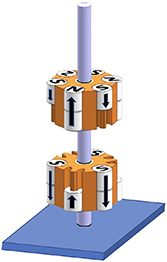
Figure 1. Magnetic barrier demonstration apparatus. An upper magnet array levitates over a lower magnet array, centred slidably on an aluminium shaft. Arrows point to magnetic north by convention.
Download figure:
Standard image High-resolution image2. Methods
2.1. The model
The apparatus shown in figure 1 consists of a base through which a 6 mm hole is drilled. A polished 6 mm aluminium rod is inserted into this hole. A pair of magnet arrays is mounted on this rod as shown. The magnet arrays each comprise a series of alternating magnets inside inside 3D-printed plastic housing. The 3D print housings are identical, except the bottom array housing accommodates a ceramic bearing. A full materials list in the online supplement [5]. A video of the apparatus can be found at https://youtu.be/6pDiiyorwec, and instructions for making a model for personal use and the 3D print files at www.tinkercad.com/things/l93kiuYv8Zl and www.tinkercad.com/things/5v6kdKpf928.
2.2. The potential barrier lab
The goal of the Coulomb barrier lab is to determine the height of the potential barrier. The upper array is raised to successively greater heights along the shaft and allowed to drop onto the lower array. The minimum height above the magnetic potential barrier at which sufficient energy is imparted to overcome the barrier is recorded as hi .
The aluminium rod is then replaced by a graduated plastic straw split down the middle with a pair of scissors (to prevent binding) and graduated in 1 cm and 1 mm increments with a fine permanent marker.
The lower array and base are placed on a gram scale sitting on an aluminium lab jack lift set to the lowest position. With the upper array removed from the system, the scale is then tared. Using the straw as a guide, the upper magnet array is placed at least 10 cm above the lower array and secured by a non-magnetic clamp. The magnetic poles (arrows in figure 1) are aligned. The initial scale value is recorded. The lift is lowered incrementally, and the scale value is recorded at each height. When the arrays are separated by a distance of 2 cm, measurements are recorded every 1 mm. These values are converted to force in newtons (grams are converted to kilograms, then multiplied by the acceleration of gravity, 9.8 m s−2), and a force/distance curve is plotted (figure 3). Forces of attraction and repulsion are equal at the x-intercept. The plot crosses the x-axis at point A where the magnetic force transitions from repulsive to attractive. This height is recorded as hf .
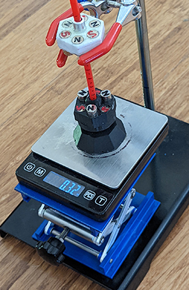
Figure 2. The experimental set-up includes an upper magnet array fixed in position over a mobile lower array resting on a gram scale and a laboratory lift. The two arrays are centered using a slidable graduated plastic straw.
Download figure:
Standard image High-resolution image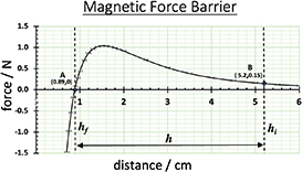
Figure 3. The force/distance curve between the upper and lower magnetic arrays shown in figure 2 crudely models the force between nuclei during nuclear fusion. Vertical error bars are too small to be shown.
Download figure:
Standard image High-resolution imageStudents may then calculate the potential energy and velocity required to overcome the magnetic potential energy barrier (neglecting friction between the shaft and upper array). The formula for gravitational potential energy is:

where  is the mass of the upper magnet array,
  is the acceleration of gravity, and
  is the difference in height between
hf
and
hi
.
is the difference in height between
hf
and
hi
.
At height h the potential energy equals the kinetic energy required to overcome the magnetic potential energy barrier according to the formula:

Solving for velocity  yields:

3. Results
The mass
m
of the upper magnet array is 0.058 12 ± 0.000 03 kg, and the height
hi
is 0.0089 ± 0.0005 m. The height at which the upper array reliably overcomes the magnetic force barrier is 0.0052 ± 0.0005 m. The difference
h
is 0.0043 ± 0.001 m. The acceleration due to gravity is 9.81 m s−2. Converting to SI units and plugging into formula (1) yields a potential energy Ep
= 2.5 × 10⁻² J to overcome the magnetic potential barrier. Thus, per formula (3), a velocity of at least  = 0.93 m s−1 is required to overcome the magnetic potential barrier [5].
4. Discussion
A pair of individual permanent magnets will either attract or repel, but combinations of magnets produce more complex force/distance curves. The alternation of single and double magnets oriented so that their magnetic axes are anti-parallel, as in figure 1, produces a magnetic force barrier analogous to forces surrounding the atomic nucleus. The preponderance of double south-facing magnetic flux ensures that the arrays will generally repel one another at far-range. However, below a certain distance threshold (i.e. the distance between arrays is less than the distance between adjacent alternating magnets within each array), double south-facing magnets on one array align and couple with the single north-facing magnetic poles on the other. The result is that at close-range, attraction exceeds repulsion, and the pair of arrays ‘fuse’ together.
As figure 3 illustrates, the force of repulsion increases as the arrays approach one another up to a maximum. If the arrays come any closer, repulsion falls off precipitously and gives way to attraction. The effect is to create a magnetic force model analogous to the forces surrounding the atomic nucleus during fusion which arise from the interplay between an electrostatic repulsive force and the strongly attractive strong nuclear force.
The primary goal of the magnetic barrier demonstration is to provide students with a conceptual appreciation for the challenges of nuclear fusion. A slight modification of experimental conditions additionally models important facets of both kinetic theory and chaos theory.
The upper array is raised at least 10 cm above the lower array and then rotated so that opposite magnetic poles align. As the upper array falls, it picks up translational kinetic energy. Upon impacting the lower array, the collision is partially elastic, i.e. the upper array bounces off the lower array due to the repulsion of opposite magnetic poles. But the collision also induces both upper and lower arrays to rotate. Thus, some of the translational energy of the falling upper array transforms into rotational kinetic energy in a demonstration of the law of conservation of energy. Close analysis of the spinning arrays immediately after collision reveals that the pair of arrays rotate in opposite directions. For every action, there is an equal and opposite reaction in accordance with Newton’s third law.
The same modification (i.e. raising the upper array at least 10 cm above the lower array and aligning opposite magnetic poles between the two arrays) may also serve to demonstrate a central tenet of chaos theory or nonlinear dynamics [6]. When a system is exquisitely sensitive to initial conditions, the final outcome is unpredictable or chaotic. No matter how much care is taken to align the magnetic poles of the top array with their opposite poles on the bottom array, the result of any two trials is never the same. Sometimes the upper array bounces off the lower array multiple times until both arrays settle into a quiet state in which the upper array levitates over the lower array. But sometimes, the upper array bounces once and then ‘fuses’ with the lower array. And at other times, the upper array bounces two, three, or four times before ‘fusing.’ In fact, the outcome is highly unpredictable and exquisitely sensitive to initial conditions, specifically the degree to which opposite magnetic poles are initially aligned.
5. Student exercises
- 1.How can the area under the curve in figure 3 be used to determine the energy required to overcome the magnetic force barrier?
- 2.The magnetic ‘Coulomb’ barrier demonstrates that opposing arrays of alternating/unequal magnets can generate a potential barrier. Maxwell unified magnetism and electricity under a single electromagnetic fundamental force [7]. Show that an alternating/unequal arrangement of point charges, where the positive charge is double the negative charge, also results in a potential barrier. Hint: position the alternating and unequal charges like the magnet positions in the magnetic ‘Coulomb’ barrier (as in figure 4), and then use Coulomb’s law to determine the forces between charges at various stages of separation.
- 3.The alternating/unequal magnet configuration of the magnetic ‘Coulomb’ barrier results in far-range repulsion and close-range attraction. Using permanent magnets, attempt to construct opposing arrays that demonstrate the opposite: far-range attraction and close-range repulsion.
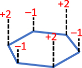


Figure 4. Alternating +2 and -1 charge in the same geometric arrange as the alternating double N and single S magnets of the Magnetic‘Coulomb’ Barrier.
Download figure:
Standard image High-resolution image

Acknowledgments
Special thanks to Dr Edward ‘Ted’ Forringer, PhD candidate Tim Lohof, Ted Seabolt M S N E, and Dr Brian Hadley Reed for their useful comments. This research received no specific grant from any funding agency in the public, commercial, or not-for-profit sectors.
Data availability statement
All data that support the findings of this study are included within the article (and any supplementary files).
Biographies

Ray Walsh is an ER physician with a bachelor’s degree in chemistry and a master’s degree in math and science education from Teachers College, Columbia University. He was a teacher trainer for the US Peace Corps in Zimbabwe, and has taught secondary math/science in Kenya (East Africa), in Harlem-(New York City), and in San Elizario, Texas, on the Mexico/US border. He is a US Air Force combat veteran, holds 9 patents, and speaks Swahili and Spanish.