Abstract
The simplex particle swarm optimization (Simplex-PSO) is a swarm intelligent based evolutionary computation method. Simplex-PSO is the hybridization of Nedler–Mead simplex method and particle swarm optimization (PSO) without the velocity term. The Simplex-PSO has fast optimizing capability and high computational precision for high-dimensionality functions. In this paper, Simplex-PSO is employed for selection of optimal discrete component values such as resistors and capacitors for fourth order Butterworth low pass analog active filter and second order State Variable low pass analog active filter, respectively. Simplex-PSO performs the dual task of efficiently selecting the component values as well as minimizing the total design errors of low pass analog active filters. The component values of the filters are selected in such a way so that they become E12/E24/E96 series compatible. The simulation results prove that Simplex-PSO efficiently minimizes the total design error to a greater extent in comparison with previously reported optimization techniques.
1 Introduction
Filters are electronic circuits that are capable of passing signals within a band of frequencies while rejecting or blocking signals of frequencies outside this band. This property of filter is called frequency selectivity. Depending on the type of elements used in construction, filters may be classified as passive or active ones. Passive filters are based on the combination of resistors, capacitors, and inductors. Active filters employ transistors or operational amplifiers in the design in addition to resistors and capacitors. Active filters are mainly used in communication, signal processing circuits and medical electronics etc.
Due to the manufacturing limitations, the task of optimal analog active filter design by hand is very difficult. Evolutionary computation may be a competent implement for automatic selection of optimal discrete component values for analog active filter design.
Conventionally, the passive components’ values used in the filter are chosen to be equal to each other. This procedure simplifies the design process but limits the flexibility of the design [1]. In order to make the design more reliable and flexible, the passive component values are chosen from E12/E24/E96 industrial series. In the E12 series each succeeding resistor or capacitor falls within the ∓10 % of the previous value. There are also E24, E48, E96 and E192 ranges for components of tighter tolerance with 24, 48, 96 and 192 different values within each decade, respectively.
If the component values of the active filter are selected either from this series or other possible preferred values, then it decreases the computational cost as well as complexity. Some of the passive components are directly chosen from the series and others are rounded off to get the nearest preferred values. In an attempt to round off to the nearest preferred values, it may happen that the cost criterion of design of the filter is not satisfied. Therefore, it becomes a challenging task to launch an exhaustive search method on all possible combinations of preferred values for obtaining the optimal design.
In the literature, various algorithms were used for optimal design of active analog filters. In [2, 3] selection of component values and topology optimization of analog active filter have been carried out using genetic algorithm (GA) and adaptive immune genetic algorithm, respectively. A fourth order voltage controlled voltage source (VCVS) Butterworth active low pass filter was designed for E12 series using Clonal selection algorithm (CSA) and CSA based designed results were compared with the results of the conventional design methods, Tabu search (TS) and GA [4]. Particle swarm optimization (PSO) [5], artificial bee colony (ABC) [6], Differential evolution (DE) and Harmony search (HS) [7] based component value selection methods have been utilized for the optimal design of the same circuit. Second order state variable active low pass filters were designed for E24 and E96 series using conventional design method and PSO [8], GA and ABC [6], DE and HS [7], artificial immune algorithm (AIA) [9] and TS [10], respectively.
Particle swarm optimization is an evolutionary algorithm developed by Eberhart et al. [11, 12]. Several attempts have been taken towards the system identification problem with conventional PSO and its modified versions [13–15]. PSO is very simple to implement and its convergence may be controlled by a few number of control parameters. The particle swarm algorithm is modified by eliminating the velocity formula in [16, 17]. A simpler and more effective PSO algorithm is presented by discarding the particle velocity in [18]. In this paper, the authors adopt an alternative superior hybrid technique called Simplex-PSO [17] for the design of fourth order Butterworth active low pass filter and second order state variable active low pass filter with E12, E24 and E96 series, respectively. The simulation results prove that Simplex-PSO efficiently minimizes the total design error to a greater extent in comparison with previously reported optimization approaches.
In [23], a novel multi-sub-swarm particle swarm optimization (MSSPSO) was proposed to find multi-solutions for multilayer ensemble pruning model. In [24], PSO was proposed to train perceptrons in predicting the outcome of construction claims in Hong Kong. In [25], a novel PSO approach was proposed for product design and manufacturing. A new hybrid PSO approach was proposed to solve structural design optimization problems in the automotive industry in [26]. A new particle swarm-based optimization method is presented for multi-objective optimization of vehicle crashworthiness in [27]. Particle swarm optimization technique is used for optimal design of analog circuits in [28]. A new improved algorithm named as Boundary Restricted Adaptive Particle Swam Optimization (BR-APSO) algorithm was proposed in [29]. Particle swarm optimization for determining fuzzy measures from data was proposed in [30].
The application of Simplex-PSO to optimal analog filter design has not yet been published till date in any previous literature. The authors chose this algorithm for the first time toward designing analog active filters.
The rest of the paper is arranged as follows: In Sect. 2, evolutionary optimization technique under consideration namely Simplex-PSO is explained briefly. Analog active low pass filers are discussed and the cost functions used in this work are formulated in Sect. 3. Extensive and elaborate simulations results are shown and discussed in Sect. 4. Finally, Sect. 5 concludes the paper.
2 Evolutionary algorithms employed
2.1 Nelder–Mead simplex method (NMSM)
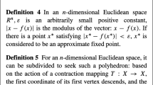
The Nelder–Mead simplex method is developed by Nelder and Mead in 1965 [19] and widely used for direct search method to solve the unconstrained optimization problems. This method employs four operations: reflection, expansion, inner contraction and outer contraction. The Nelder–Mead simplex method starts with a simplex in domain of the function to be minimized, then modifies the simplex in four different ways until the simplex is very flat.
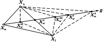
A D-dimensional simplex is a geometrical figure which consists of (D + 1) points. The simplex method starts with (D + 1) initial points randomly in the search space and then calculates the fitness value of each point. It finds the best point X b where the fitness function is the lowest, the worst point X W where the fitness function is the highest and the second worst point X 1 where the fitness function is the second highest. Then simplex method takes a series of operations including reflection, expansion, and contraction to find a better point and replaces the worst point. This process is repeated until a termination criterion is satisfied. \( X_{W}^{c} \) is the centroid of all points except the worst point X W , \( X_{W}^{r} \) is the reflection point, \( X_{W}^{e} \) is the expansion point, \( X_{W}^{ic} \) is the inner contraction point, \( X_{W}^{oc} \) is the outer contraction point as shown in Fig. 1. The four operations of NMSM are written as
where \( X_{W}^{*} \) denotes a reflection point, expansion point, inner contraction point or outer contraction point of the worst point X W ; γ denotes reflection coefficient, expansion coefficient, inner contraction coefficient or outer contraction coefficient, respectively, when it is in different intervals. \( X_{W}^{c} \) is given by
where m denotes the number of simplex points and X i is a point of a simplex with m points.
2.2 Simplex-PSO
\( X_{W}^{c} \), X b and \( X_{b}^{c} \) represent the centroid of all points except the worst point X W , the best point and the centroid of all points except the best point, respectively.
\( X_{W}^{c} \) is given by
\( X_{b}^{c} \) is given by
Hence, substituting (3) into (1) yields the equation
Since (γ + 1) ≤ 3, let γ = 3α − 1, 0 ≤ α ≤ 1, then (5) becomes
Equation (6) is derived from the worst point; if the form of (6) is popularized to other simplex points and factor γ 0 is introduced into the first term \( X_{W}^{c} \), a common form will be given by
where \( \gamma_{1} = \frac{3\alpha }{m - 1} \), γ 2 = 3α − 1. Point X i is looked as the ith particle of the kth iteration, i.e., X i (k) and X i is looked as the ith particle of the (k + 1)th iteration reasonably, i.e., X i (k + 1). The discrete equation corresponding to (7) is written as
Let γ 0 = c 0, \( \gamma_{1} = c_{1} rand_{1} () \) and \( \gamma_{2} = c_{2} rand_{2} () \), where c 0, c 1 and c 2 are constants. Hence, the equivalent form of (8) is
Equation (9) is derived from the Nelder–Mead simplex method and similar to PSO, so it is called Simplex-PSO.
According to Eq. (9), the reference objectives of Simplex-PSO are the best particle and the centroid of the particles except the best particle. From information processing, the centroid reflects synthetic information of all particles and is influenced by changes of all particles’ position. Therefore, the centroid reference objective is updated promptly and effectively.
The Simplex-PSO consistently maintains asymptotic stability and asymptotic convergence [17], if
The algorithmic steps of Simplex-PSO algorithm are as follows:
- Step 1:
-
Initialization: Population (swarm size) of particle vectors, n P ; dimension of the optimization problem, D; maximum iteration cycles; target error; fixing values of c 0 = 0.8, c 1 = 0.6 and c 2 = 0.08; define limits of design parameters, select initial searching points
- Step 2:
-
Computation of cost function (CF) for each point, these are the initial best points
- Step 3:
-
Update the points using (9) and checking against the limits of the design parameters; finally, computation of the updated CF values for each points
- Step 4:
-
Update the worst points by better points; replace the updated points as initial points for step 3
- Step 5:
-
Iteration continues from step 3 till the maximum iteration cycle or the grand minimum error becomes less than the target error; finally, return the best point of the minimum CF value and its corresponding parameters are the optimal discrete component values of resistors and capacitors.
3 Active low pass filter design
3.1 Butterworth filter design
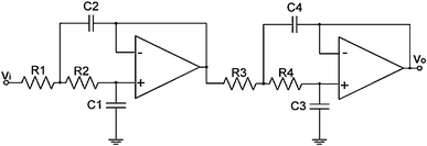
The Butterworth (BW) filter is designed to have as flat a frequency response as possible in the pass band. It is also referred to as a maximally flat magnitude filter. This type of filter is a good ‘all rounder’, simple to understand and is efficient for applications such as audio processing etc. The fourth order low pass BW active filter can be designed by cascading two second order blocks [4]. The circuit diagram for fourth order low pass BW active filter is shown in Fig. 2 and it behaves like a voltage controlled voltage source (VCVS). The transfer function of the fourth order BW filter is given in (10).
where ω c1 and ω c2 are the cut-off frequencies of two second order filters, Q 1 and Q 2 are the quality factors of two second order filters, respectively.
The cut-off frequencies and the quality factors for both the cascaded filters with respect to the circuit components can be written, respectively, as:
So, the transfer function of a fourth order low pass BW filter according to Fig. 2 can be written as:
In this paper cut-off frequencies of both the second order filters used for cascading are chosen to be 10 krad/s. The quality factors Q 1 and Q 2 are chosen as 1/0.7654 and 1/1.8478, respectively [5, 6]. The goal of this work is to carefully select the components of the filter and to minimise the cost function (CF) simultaneously. The CF is designed by taking the components of the active filter only [5, 6]. The design error given in (20) is the summation of cut-off frequency deviation(Δω)and quality factor deviation(ΔQ)as given in (18) and (19) respectively.
ω c = 10 krad/s.
In terms of the components of the filter the frequency deviation can be written as:
The quality factor deviation can be written as:
The total cost function is also the design error, which can be written as:
The same cost function is considered in [5, 6]. The CF BW given in (20) is to be minimised by the Simplex-PSO algorithm. Simplex-PSO estimates the component values of the Butterworth filter for different preferred series.
Firstly, Butterworth filter is designed with the components that are compatible with E12 series. Each component used in the design is chosen to take value in the range of 103–106 Ω for the resistors and 10−9–10−6 F for the capacitors. If the values of the resistors and capacitors lie outside this range, then they must be discarded as they are not compatible with the E12 series.
Any row of the population matrix can be initialized as a vector:
From the elements of any row vector of the population matrix, the values of the resistors and capacitors can be calculated as (21).
For E12 series, the design constraints for resistors and capacitors are given as follows:
Secondly, Simplex-PSO algorithm estimates the component values of the BW filter that are compatible with E24 series. The values of the resistors and capacitors lie within the range of 103–106 Ω and 10−9–10−6 F, respectively. For E24 series, the design constraints for resistors and capacitors are given as follows:
Thirdly, Simplex-PSO algorithm estimates the component values of the BW filter that are compatible with E96 series. The values of the resistors and capacitors lie within the range of 103–106 Ω and 10−9–10−6 F, respectively. For E96 series, the design constraints for resistors and capacitors are given as follows:
3.2 State variable filter design
State space model is directly realized in state variable filter (SVF). The SVF is shown in Fig. 3 and is well explained in [20].
The response of a second order low pass SVF circuit is completely specified by cut-off frequency \( (\omega_{SVF} = 2\pi f_{SVF} ) \) and quality factor (Q SVF ) as given by:
The target cut-off frequency (ω 0) is 10 krad/s and target quality factor (Q t ) is 0.707 [6, 7]. The design error given in (28) is the summation of cut-off frequency deviation (Δω 0) and quality factor deviation (ΔQ t ) as given in (26) and (27) respectively.
In terms of the components of the filter the frequency deviation parameter can be written as:
The quality factor deviation parameter can be written as:
The total cost function is also the total design error, which can be written as:
The same cost function is also considered in [6, 7]. The CF SVF given in (28) is to be minimized by the Simplex-PSO algorithm. Simplex-PSO estimates the component values of the SVF for E12, E24 and E96 series, respectively. Each component used in the respective design is chosen to take a value in the range of 103–106 Ω for the resistors and 10−9–10−6 F for the capacitors. Since the probable values vary from three decade ranges, a coding scheme is used and is given as:
For E12 series, the design constraints for resistors and capacitors are given as follows:
For E24 series, the design constraints for resistors and capacitors are given as follows:
For E96 series, the design constraints for resistors and capacitors are given as follows:
3.3 Multi-parameter sensitivity analysis
The relative or normalized sensitivity (S) can be defined as the cause and effect relationship between the circuit elements’ variations, and the resulting changes in the performance responses [21, 22]. Furthermore, in the design of analog ICs, the lowest sensitivity is much desired.
Let f i (X) be an objective function (performance response), where \( X = [x_{1} , \ldots .x_{n} ]^{T} \) is the vector of the design variables. It is possible to relate small changes in the response of the performance \( (\partial f_{i} ,i \in [1,m]) \) to variations in the design variables \( (\partial x_{j} ,j \in [1,n]) \). It leads to the single parameter sensitivity definition given by,
According to (30), there is one sensitivity for each objective function f and for each variable in X. Then, it is possible to define the multi-parameter sensitivity which sums the different single sensitivities regarding the different variables for each objective as follows [22]:
where \( S_{{x_{i} }}^{{f_{j} }} \) is calculated by (30); \( \sigma_{{x_{i} }} \) is a variability parameter of x i and the square root is used to preserve the same units. In this way, the multi-parameter sensitivity for the cost functions CF BW (for BW filter) and CF SVF (for SVF), respectively, can be calculated as:
where x i is replaced by variable resistance parameter R i or, variable capacitance parameter C i .
4 Simulation results and discussions
In this work, Simplex-PSO is used to estimate the component values of the BW low pass filter and SVF low pass designs for different preferred series. Initial population matrix is 10 × 16 which is given in (34). For Simplex-PSO, the parameters are taken as follows: c 0 = 0.8, c 1 = 0.6 and c 2 = 0.08, for each design. These parameters have been tuned by several trial runs. The optimization program for each design was run in MATLAB 7.5 version on core (TM) 2 duo processor, 3.00 GHz with 2 GB RAM. The algorithm was run with an upper bound of 1,000 iterations. The algorithm was trial run for 50 times for each series and the best results have been reported in this paper.
4.1 Results for the designed Butterworth filter
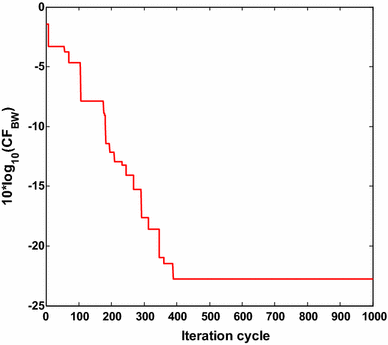
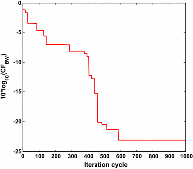
The component values of fourth order BW active low pass filter are selected from E12, E24 and E96 series, respectively, with a target error CF BW value <0.0057. Table 1 shows the component values and the CF BW values obtained by conventional PSO, other evolutionary optimization methods [4, 5, 6, 7] and the proposed Simplex-PSO algorithm for BW filter design with E12 series. For E12 series, Simplex-PSO has met the target error requirement at iteration 397 in 14.511 s and CF BW value is obtained as 0.0038, which is the least as compared to previously reported results as shown in Table 1. Thus it is proved that Simplex-PSO is superior than the other reported evolutionary techniques for optimal BW active low pass filter design. Five component values of Simplex-PSO based design of BW filter belong to E12 series. C1 value can be realized by connecting 8.2 and 0.39 nF in parallel. Similarly C2 is the parallel combination of 56 and 6.8 nF. R3 value can be realized by connecting 100 and 1.2 kΩ in series. Figure 4 shows the plot of 10log10 (CF BW ) versus iteration cycle for BW low pass filter design for E12 series. The grand minimum 10log10 (CF BW ) of −24.2022 dB is obtained by the proposed algorithm, to prove its optimizing superiority.
Table 2, illustrates the component values and the cost function (CF BW ) obtained by Simplex-PSO algorithm for BW filter design with E24 series. For E24 series, Simplex-PSO achieves the target error requirement at iteration cycle 589 in 23.022 s and CF BW value is obtained as 0.0031. Four component values of Simplex-PSO based design of BW filter belong to E24 series. R3 value can be realized by connecting 18 and 1.5 kΩ in series. R4 is the series combination of 12 and 1.6 kΩ. C2 is the parallel combination of 51 and 30 nF. C4 is the parallel combination of 6.2 and 0.56 nF. Figure 5 shows the plot of 10log10 (CF BW ) versus iteration cycle for BW low pass filter design for E24 series. The minimum 10log10 (CF BW ) obtained by Simplex-PSO is
−25.0864 dB as shown in Fig. 5. There are no previously reported results for comparison in this E24 series.
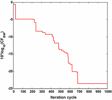
Table 3 demonstrates the component values and the design error (CF BW ) obtained by Simplex-PSO algorithm for BW filter design with E96 series. For E96 series, Simplex-PSO has met the target error requirement at iteration cycle 685 in 25.605 s and CF BW value is obtained as 0.0030. All component values of Simplex-PSO based design of BW filter belong to E96 series. Figure 6 shows the plot of 10log10 (CF BW ) versus iteration cycle for BW low pass filter design for E96 series. There are no previously reported results for comparison in this E96 series. The nearly same order grand minimum 10log10 (CF BW ) values are consistently obtained by the Simple-PSO to prove its robustness.
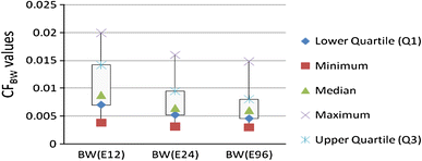
Figure 7 shows the box and whisker plots of Simplex-PSO algorithm for BW low pass filter designs with E12, E24 and E96 series, respectively. The algorithm has been run 50 times for each series and the resulting CF BW values obtained in each run have been used for box and whisker plots, respectively. Upper and lower ends of boxes represent the 75th and 25th percentiles. Median is represented by the green colour. The whiskers are lines extending from each end of the boxes to show the extent of the rest of the data. Outliers are data with values beyond the ends of the whiskers.
For E12 series, the median value of CF BW is 0.0088 and the range of variation of CF BW values is 0.0038–0.0199. For E24 series, the median value of CF BW is 0.0064 and the range of variation of CF BW values is 0.0031–0.0160. For E96 series, the median value of CF BW is 0.0060 and the range of variation of CF BW values is 0.0030–0.0148. The median value and the range of CF BW is the lowest for E96 series and the highest for E12 series. So, Simple-PSO performs more stably for the design of BW low pass filter for E96 series.
In order to validate the results obtained through Simplex-PSO optimizations, BW low pass filters are simulated using LM741 op-amp macro model in Simulation Program for integrated circuit emphasis (SPICE) simulator [5, 6].
A macro model uses resistors, capacitors, inductors, controlled sources, and some active devices (mostly diodes) to capture the essence of the performance of a complex circuit like an op-amp without modelling every internal component of the op-amp. The advantage of the macro model is to permit the trade-off of model complexity for decreased simulation time. An operational amplifier can be simulated in different ways. The first method is to model the amplifier by resistors, capacitors and dependent sources. As an example an ideal op-amp is easily simulated using a voltage dependent voltage source. The second option uses actual transistors to model the op-amp. The device library contains nonlinear models of the most common op amps. SPICE has macro models for the linear amplifiers LM324 and LM741. LM741 is most common and general purpose IC op-amp. LM 741 is used in closed loop configuration and LM324 in open loop configuration. Advantages of LM741 over LM324 are
-
Short circuit protection
-
Excellent temperature stability
-
Internal frequency compensation
-
High input voltage range
-
Null of offset
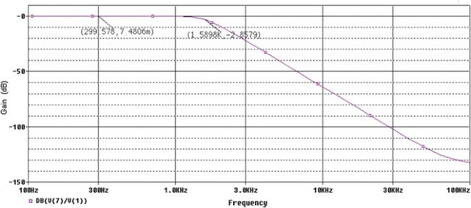
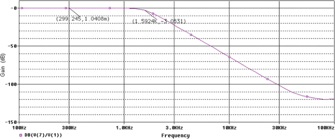
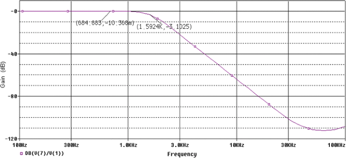
Due to those advantages, LM 741 gives more accurate, practical and reliable results over LM 324. The amplitude responses of the BW fourth order low pass filters having component values compatible with E12, E24 and E96 series are shown in Figs. 8, 9, 10, respectively. In those figures X-axis represents the frequency and Y-axis is the amplitude response in decibels. V (1) and V (7) represent the input and output voltage of the BW active low pass filter for SPICE simulation. Since ω c is the frequency point which the output of the circuit is −3 dB of the nominal pass band value, those points are also marked on those figures, respectively. SPICE simulation results show that the proposed method of optimization provides a maximally flat response in the pass band and cut-off frequencies of 9.993, 10.009 and 10.009 krad/s, respectively. So, it can be concluded that whatever grand optimal parameter values obtained by the Simplex-PSO for BW filters are accurate enough so that after simulation by SPICE, the above mentioned cut-off frequencies are very near to or, having very small (0.007, 0.009, 0.009 krad/s) deviations from the desired 10 krad/s cut-off frequency with maximally flat pass band responses.
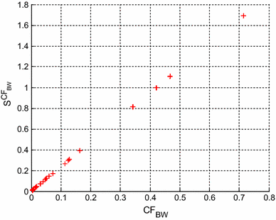
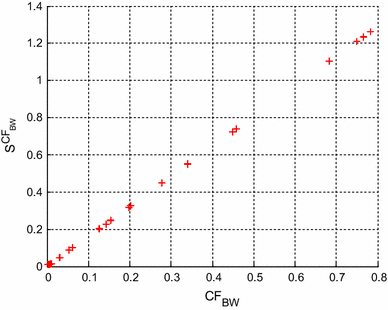
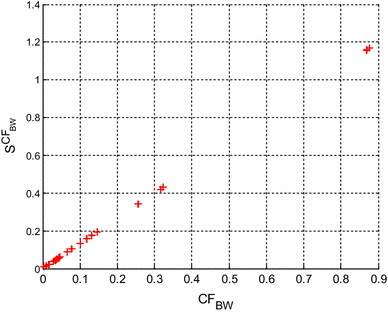
Figures 11, 12 and 13 represent the multi-parameter sensitivity of CF BW evaluated by (32), with σ = 1 % for the BW fourth order low pass filters having component values compatible with E12, E24 and E96 series, respectively. Figures 11, 12 and 13 show that the lower values CF BW exhibit lower multi-parameter sensitivity, so the optimal BW low pass filter design can be guaranteed.
4.2 Results for the designed state variable filter
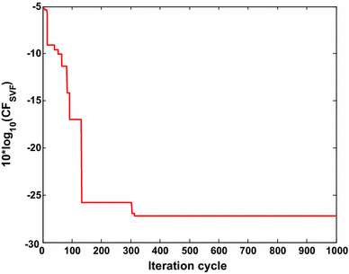
In SVF low pass design the component values are selected from E12, E24 and E96 series, respectively. For E12 series compatible design of SVF, the target error value CF SVF is aimed to be <2 × 10⁻³. Table 4 shows the component values and the CF SVF obtained by Simplex-PSO algorithm for SVF design with E12 series. For E12 series, CF SVF value is obtained as 0.0019 at iteration cycle 313 in 17.179 s. Six component values of Simplex-PSO based design of SVF low pass belong to E12 series. R1 value can be realized by connecting 10 and 4.7 kΩ in series. R4 is the series combination of 22 and 5.6 kΩ. Figure 14 shows the plot of 10log10 (CF SVF ) versus iteration cycle for SVF low pass design for E12 series. There are no previously reported results for comparison in this E12 series.
The minimum 10log10 (CF SVF ) obtained by the algorithm = −27.2125 dB.
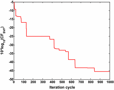
For E24 series compatible design of SVF, the target error value CF SVF is aimed to be <3.2 × 10⁻⁵. Table 5 illustrates the component values and the CF SVF values obtained by other reported evolutionary optimization techniques and the Simplex-PSO algorithm for SVF design with E24 series. For E24 series, the value of CF SVF becomes 2.8584 × 10⁻⁵ at iteration cycle 841 in 43.627 s. So, Simplex-PSO shows the least and the best CF SVF as compared to the previously reported results [6, 7, 8] for SVF low pass design with E24 series. One component value of Simplex-PSO based design of SVF belongs to E24 series. R1 is the series combination of 220 and 1 kΩ, R2 is the series combination of 6.8 kΩ and 160 Ω, R4 is the series combination of 180 and 10 kΩ, R5 is the series combination of 51 kΩ and 43 Ω and R6 is the series combination of 1.8 and 12 kΩ.C1 is the parallel combination of 43 and 3.9 nF. C2 value can be realized by connecting 10 and 0.27 nF in parallel. Figure 15 shows the plot of 10log10 (CF SVF ) versus iteration cycle for SVF design (E24 series). The grand minimum of the same 10log10 (CF SVF ) = −45.4388 dB is obtained by the Simplex-PSO to prove optimizing superiority over other algorithms.
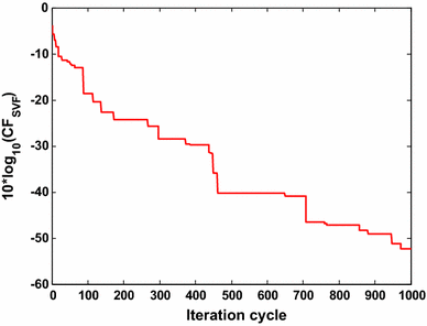
For E96 series compatible design of SVF, the target error value CF SVF is aimed to be <1.6 × 10⁻⁵. Table 6 shows the component values and the CF SVF values achieved by the reported optimization methods and the Simplex-PSO algorithm for SVF low pass design with E96 series. For E96 series, the grand least CF SVF value is obtained as 5.8011 × 10⁻⁶ at iteration cycle 973 in 51.848 s. Therefore, Simplex-PSO shows the least and the best CF SVF as compared to other evolutionary optimization techniques [6, 7, 8]. Six component values of Simplex-PSO based design of SVF belong to E96 series. R1 is the series combination of 150 and 3.09 kΩ. R4 value can be realized by connecting 20 kΩ and 24.9 Ω in series. Figure 16 shows the plot of 10log10 (CF SVF ) versus iteration cycle for SVF low pass design for E96 series. The least grand minimum value of 10log10 (CF SVF ) = −52.3649 dB is obtained by using the proposed algorithm, which thus proves its superior optimization capability.
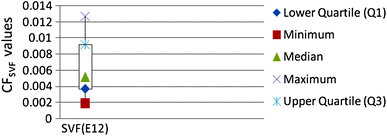
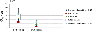
Figure 17 shows the box and whisker plots of Simplex-PSO based SVF low pass second order design with E12 series and Fig. 18 for E24 and E96 series over 50 runs, for each series.
For E12 series, the median value of CF SVF is 0.0052 and the range of variation of CF SVF values is 0.0019–0.0127. For E24 series, the median value of CF SVF is 4.7 × 10⁻⁵ and the range of variation of CF SVF values is 2.8584 × 10⁻⁵–9.63 × 10⁻⁵. For E96 series, the median value of CF SVF is 19.5 × 10⁻⁶ and the range of variation of CF SVF values is 5.8011 × 10⁻⁶–39.8511 × 10⁻⁶. The median value and the range of CF SVF is the lowest for E96 series and the highest for E12 series. So, Simple-PSO performs more stably for the design of SVF low pass filter for E96 series.
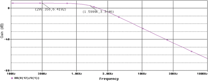
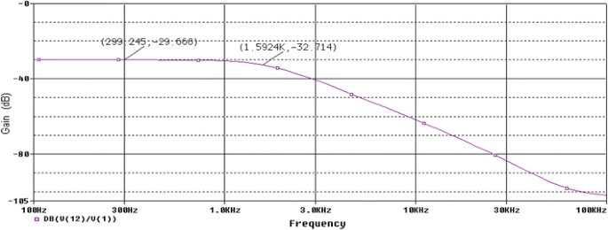
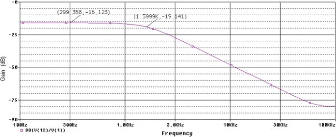
Second order state variable low pass filters are simulated using LM741 op-amp macro model in SPICE simulator [6, 8] having component values compatible with E12, E24 and E96 series, respectively achieved by Simplex-PSO. The amplitude responses of the SVF having component values compatible with E12, E24 and E96 series are shown in Figs. 19, 20 and 21, respectively. In those figures X-axis represents the frequency and Y-axis is the amplitude response in decibels [gain (dB)]. V (1) and V (12) represent the input and output voltages of the SVF low pass for SPICE simulation. As ω c is the frequency point which the output of the circuit is −3 dB of the nominal pass band value, those points are also marked on those figures, respectively. SPICE simulation results prove that the proposed method provides a maximally flat response in the pass band and a cut-off frequency of 10.056, 10.009 and 10.056 krad/s, respectively. So, it can be concluded that whatever grand optimal parameter values obtained by the Simplex-PSO for SVF filters are accurate enough so that after simulation by SPICE, the above mentioned cut-off frequencies are very near to or, having very small deviations from the desired 10 krad/s cut-off frequency with maximally flat pass band responses.
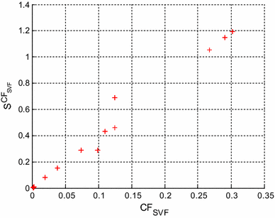
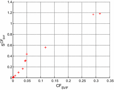
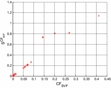
Figures 22, 23 and 24 correspond to the multi-parameter sensitivity of CF SVF evaluated by (33), with σ = 1 % for the SVF second order low pass filters having component values compatible with E12, E24 and E96 series, respectively. Figures 22, 23 and 24 show that the lower values CF SVF exhibit lower multi-parameter sensitivity, so the optimal SVF low pass filter design is guaranteed.
5 Conclusions
Automation of analog active filter optimization is a very difficult and time consuming task. The emphasis of this work is optimal designing of Butterworth and state variable filers using actually existing components, which will yield feasible circuits. In this work the utilization of evolutionary algorithm like Simplex-PSO is investigated for optimal analog active filter design. Selections of passive components from different manufactured series are performed by Simplex-PSO for the fourth order Butterworth active low pass filter and the second order State Variable active low pass filter. Selection of the optimal own parameters for Simplex-PSO are very crucial on minimizing total design error value thus affecting filter performance. Simplex-PSO does more fine-tuning of optimal component values to decrease the total error value and execution time. Considering Butterworth filter design with E12 series, Simplex-PSO achieves less total design error than the reported methods and provides the least total design error for E96 series. For state variable filter design with E24 and E96 series, Simplex-PSO minimizes the total design error with respect to the reported methods with minimum number of iteration cycles. From SPICE simulation results it is clear that Simplex-PSO based filters have maximally flat response in the pass band and less cut-off frequency deviation. Thus Simplex-PSO proves itself to be an efficient optimization technique for optimal selection of components values for analog active filter design. The performance of analog electronic circuit often deviates from the ideal design target due to rounding of the calculated component values to preferred ones. The parallel (for capacitor) or series (for resister) combinations of discrete circuit components for the design of active analog filter are not preferred in order to avoid large component area and noise. Due to avoid those disadvantages, discrete components should choose directly from the manufacturing series. Future directions would be to evaluate the optimization performance of other metaheuristic algorithms on more complex analog filter structures with particular design specifications.
References
Sanchez-Sinencio E, Silva-Martinez J (2000) CMOS transconductance amplifiers, architectures and active filters: a tutorial. IEEE Proc Circuits Devices Syst 147(1):3–12
Zebulum RS, Pacheco MA, Vellasco M (1999) Artificial evolution of active filters: a case study. In: Proceedings of the 1st NASA DoD workshop on evolvable hardware, pp 66–75
Xu H, Ding Y (2009) Optimizing method for analog circuit design using adaptive immune genetic algorithm. In: Proceedings of the international conference on frontier of computer science and technology, pp 359–63
Jiang M, Yang Z, Gan Z (2007) Optimal components selection for analog active filters using clonel selection algorithm. Proc ICICI LNCS 4681:950–959
Vural RA, Yildirim T (2010) Component value selection for analog active filter using particle swarm optimization. In: Proceedings of the 2nd IEEE international conference on computer and automation engineering, vol 1, pp 25–28
Vural RA, Yildirim T, Kadioglu T, Basargan A (2012) Performance evaluation of evolutionary algorithms for optimal filter design. IEEE Trans Evol Comput 16(1):135–147
Vural RA, Bozkurt U, Yildirim T (2013) Analog active filter component selection with nature inspired meta heuristics. Int J Electron Commun (AEÜ) 67(3):197–205
Vural RA, Yildirim T (2010) State variable filter design using particle swarm optimization. In: Proceedings of the XIth international workshop on symbolic and numerical methods, modeling and applications to circuit design, pp 1–4
Kalinli A (2004) Optimal circuit design using immune algorithm. Proc ICARIS LNCS 3239:42–52
Kalinli A (2006) Component value selection for active filters using parallel Tabu search algorithm. Int J Electron Commun (AEÜ) 60(1):85–92
Kennedy J, Eberhart R (1995) Particle swarm optimization. Proc IEEE Int Conf Neural Netw 4:1942–1948
Eberhart R, Shi Y (1998) Comparison between genetic algorithm and particle swarm optimization. In: Evolutionary programming-VII, Springer, New York, pp 611–616
Luitel B, Venayagamoorthy GK (2010) Particle swarm optimization with quantum infusion for system identification. Eng Appl Artif Intell 23:635–649
Yu X, Liu J, Li H (2009) An adaptive inertia weight particle swarm optimization algorithm for IIR digital filter. In: IEEE international conference on artificial and computational intelligence, pp 114–118
Fang W, Sun J, Xu W (2009) A new mutated quantum behaved particle swarm optimizer for digital IIR filter design. EURASIP J Adv Signal Process 2009 (article ID 367465):1–7
Kennedy J (2003) Bare bones particle swarms. In: IEEE swarm intelligence symposium, USA, pp 80–87, 24–26 April 2003
Hong-feng X, Guan-Zheng T (2010) A novel particle swarm optimizer without velocity: simplex-PSO. J Central South Univ 17(2):349–356
Wang H, Zhi-shu L (2007) A simpler and more effective particle swarm optimization. J Softw 18(4):861–868
Nelder JA, Mead R (1965) A simplex method for function minimization. Comput J 7(2):308–313
Schaumann R, Valkenburg MV (2001) Design of analog filters. Oxford University Press, New York
Mohan P (2010) Sensitivity analysis of third and fourth-order filters. Circuits Syst Signal Process 29(5):999–1005
Gomez G, Cuautle ET, de la Fraga LG (2013) Richardson extrapolation-based sensitivity analysis in the multi-objective optimization of analog circuits. Appl Math Comput 222:167–176
Zhang J, Chau K-W (2009) Multilayer ensemble pruning via novel multi-sub-swarm particle swarm optimization. J Univ Comput Sci 15(4):840–858
Chau KW (2007) Application of a PSO-based neural network in analysis of outcomes of construction claims. Autom Constr 16(5):642–646
Ali Rıza Yıldız (2009) A novel particle swarm optimization approach for product design and manufacturing. Int J Adv Manuf Technol 40(5–6):617–628
Yildiz AR (2012) A new hybrid particle swarm optimization approach for structural design optimization in the automotive industry 226(D10):1340–1351
Yildiz AR, Solanki KN (2012) Multi-objective optimization of vehicle crashworthiness using a new particle swarm based approach. Int J Adv Manuf Technol 59(1–4):367–376
Fakhfakh M, Cooren Y, Sallem A, Loulou M, Siarry P (2010) Analog circuit design optimization through the particle swarm optimization technique. Analog Integr Circuits Signal Process 63(1):71–82
Rana S, Jasola S, Kumar R (2013) A boundary restricted adaptive particle swarm optimization for data clustering. Int J Mach Learn Cybern 4(4):391–400
Wang X-Z, He Y-L, Dong L-C, Zhao H-Y (2011) Particle swarm optimization for determining fuzzy measures from data. Inf Sci 181(19):4230–4252
Author information
Authors and Affiliations
Corresponding author
Rights and permissions
About this article
Cite this article
De, B.P., Kar, R., Mandal, D. et al. Optimal selection of components value for analog active filter design using simplex particle swarm optimization. Int. J. Mach. Learn. & Cyber. 6, 621–636 (2015). https://doi.org/10.1007/s13042-014-0299-0
Received:
Accepted:
Published:
Issue date:
DOI: https://doi.org/10.1007/s13042-014-0299-0


