It was a hard decision to start from scratch with a new project for this next gen effort since the #LiFePO4wered/Pi project has such good traction and a gazillion likes, but the more I thought about it, the more I realized that starting with a clean slate would allow me the freedom to make this what people want it to be instead of feeling shackled by legacy, and at the same time prevent confusion about the different generations. A new project also allows me to enter it for the 2017 Hackaday Prize. :)
There are some issues with the current #LiFePO4wered/Pi design that I hope to address in this Next Gen effort:
1. Make it easier to assemble. The two-PCB arrangement with the charger on the bottom and power manager on top makes for a nice and compact unit, but it takes too much time to assemble. The original design sprang from a desire to provide an example application for the #LiFePO4wered/USB, but the #LiFePO4wered/Pi has turned out to be a much more popular product in its own right. So this will be a single-board setup with the charger and power manager both on one PCB, significantly reducing assembly time and cost. It is the best way to reduce cost and support higher volume.
2. Alleviate power limitations due to physical size. Power supplies unfortunately generate quadratically more waste heat as the current goes up (P = I^2 * R), and the tiny PCBs in the current design have a hard time sinking this heat away. Customers always want more power, but recent experiments with higher power on the current physical design have convinced me that the only way to allow more power is a bigger PCB with more copper.
3. Improve hackability. For a product targeted at hardware hackers, the current design is not the most hacker friendly, mostly because there is very little room due to the small size. Customers want to connect different power sources, have the on/off button and LED remotely located, etc. The current design has some tiny surface mount pads to allow such things, but decent sized through-hole pads and more configuration and customization options would definitely be welcome.
4. Make load current independent of charge current. Some people don't need a big battery for long untethered run time, they just want a little bit of juice, enough to shut the system down safely when external power fails. But in the current design, maximum UPS load current is linked with charge current, which in turn dictates battery size. I hope to separate these two concerns and provide high load current with a small battery as well.
5. Improve physical stability. This isn't usually a problem, but the current mounting method with one screw and the weight of the battery supported on the 4-pin connector between the boards is not ideal. I plan to use a 40-pin header and connect to at least 2 screw holes.
So here is my current plan to make this happen:
- Start with a Pi Zero-sized PCB, extended past the GPIO header so the battery can still sit next to the Pi, but upside-down. Have one PCB design that can accommodate both the 14500 and 18650 cells. The 18650 will be located more forward than in the current design, making sure it doesn't stick out farther than the USB ports on a Model B+ any more.
- The circuitry will be over the Raspberry Pi as is the case for most HATs. The components will be mounted on the bottom of the PCB, with only the on/off button (mechanical switch) and LEDs mounted on top. Most of the top of the PCB will be copper plane for heat sinking, on which an additional heat sink can be mounted if deemed necessary for high power applications.
- There will be through holes for remote on/off button and LEDs, to easily connect input power other than USB, give access to 3.2V battery power and switched 5V output power, connect external LiFePO4 cells and loads, and adjust the charger's MPP for use with solar panels.
Anything I've missed? Comments and requests are not only welcome but highly encouraged!
 Patrick Van Oosterwijck
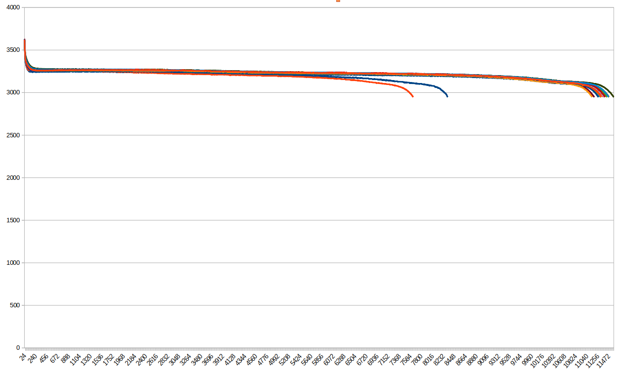
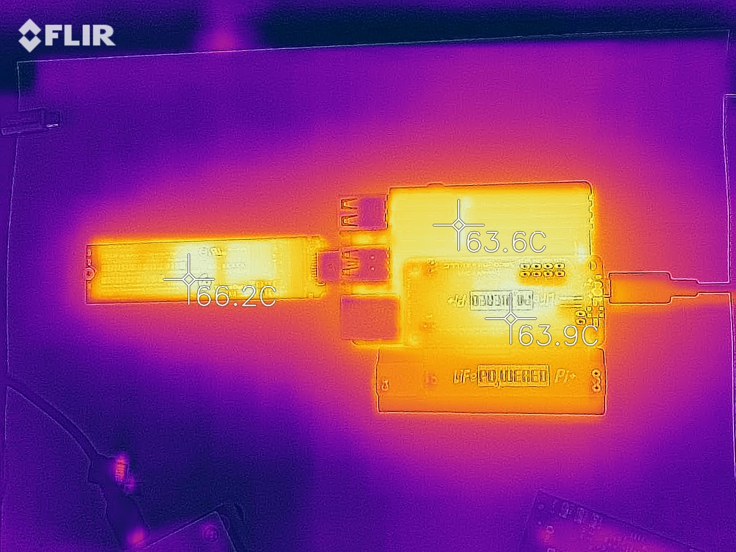
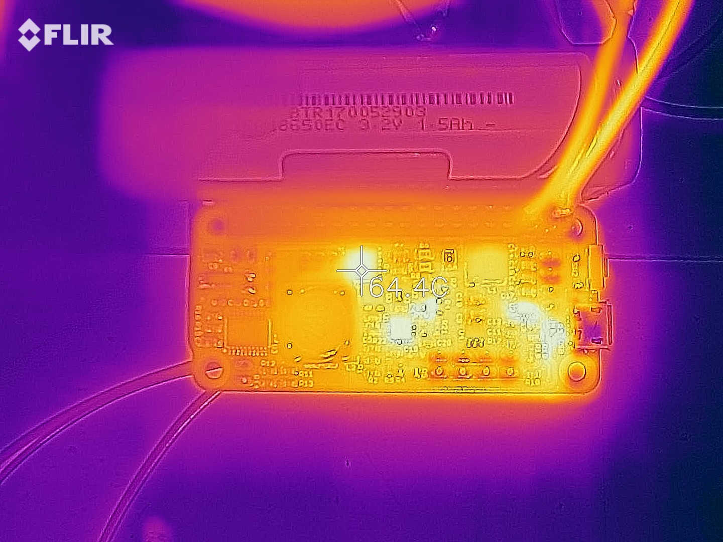
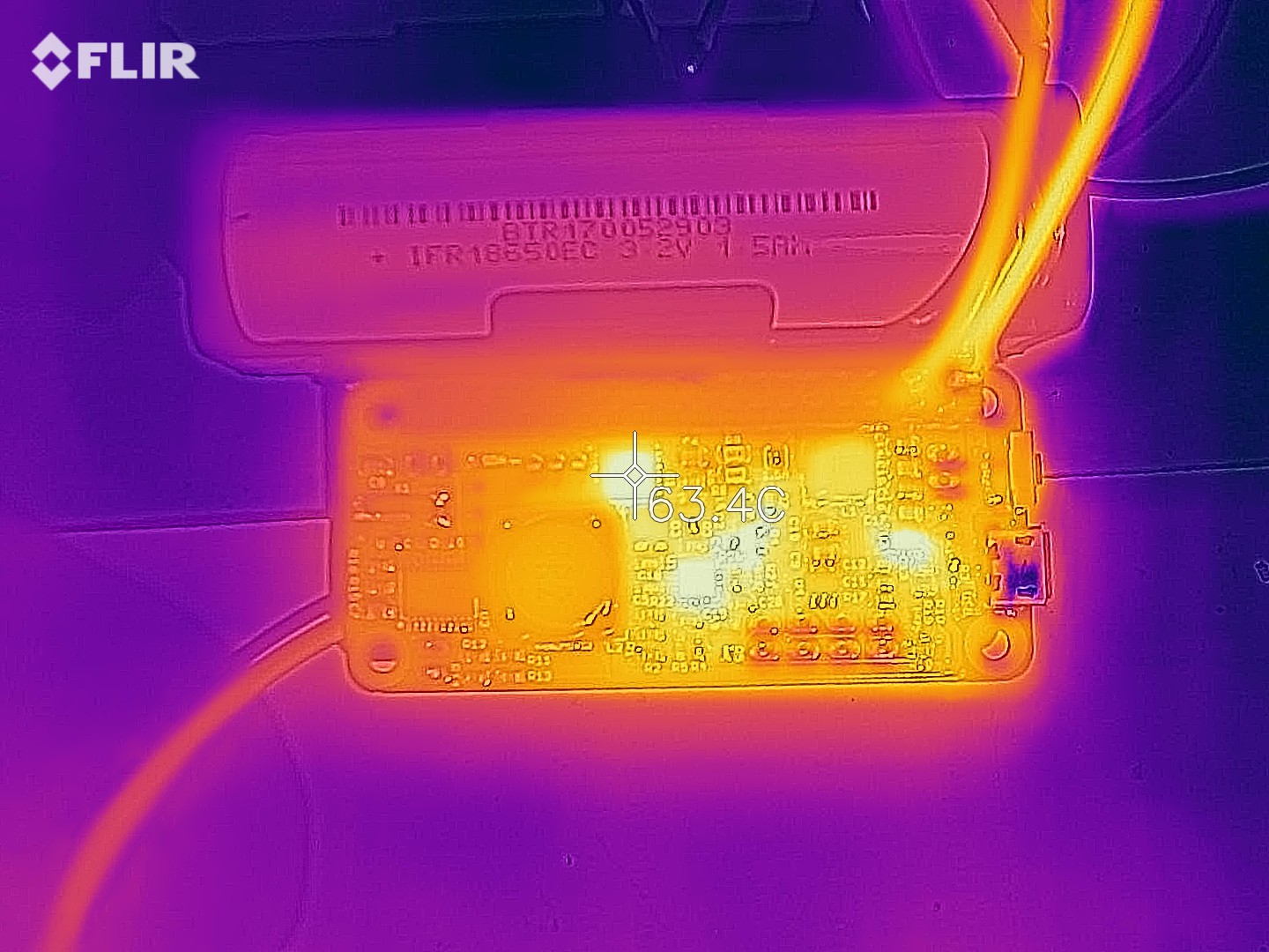
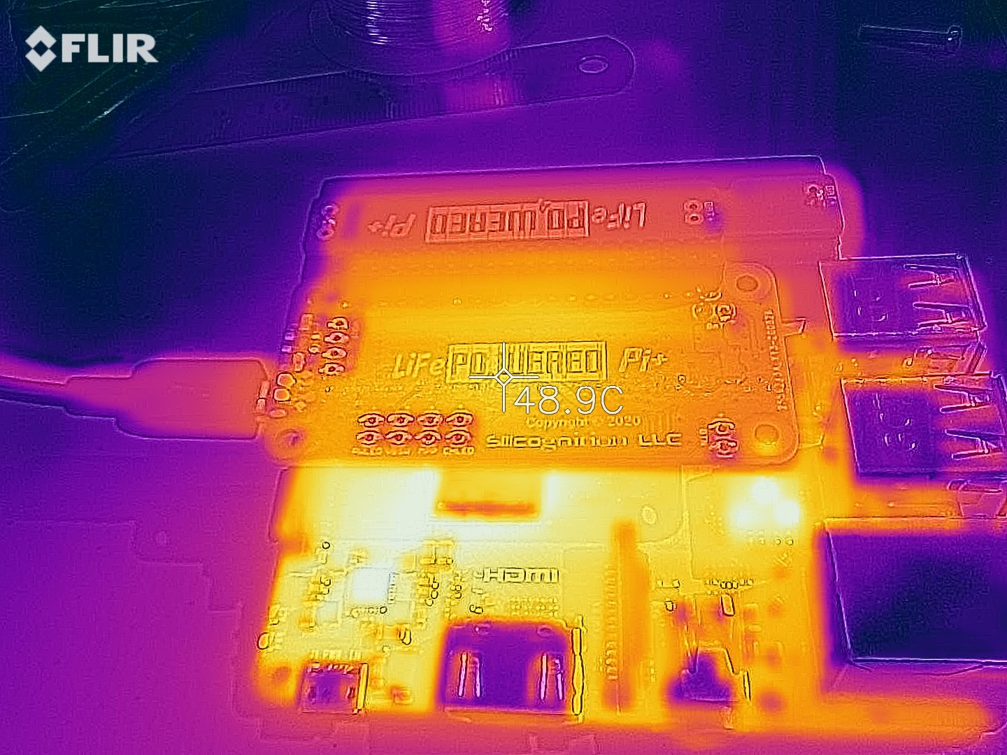
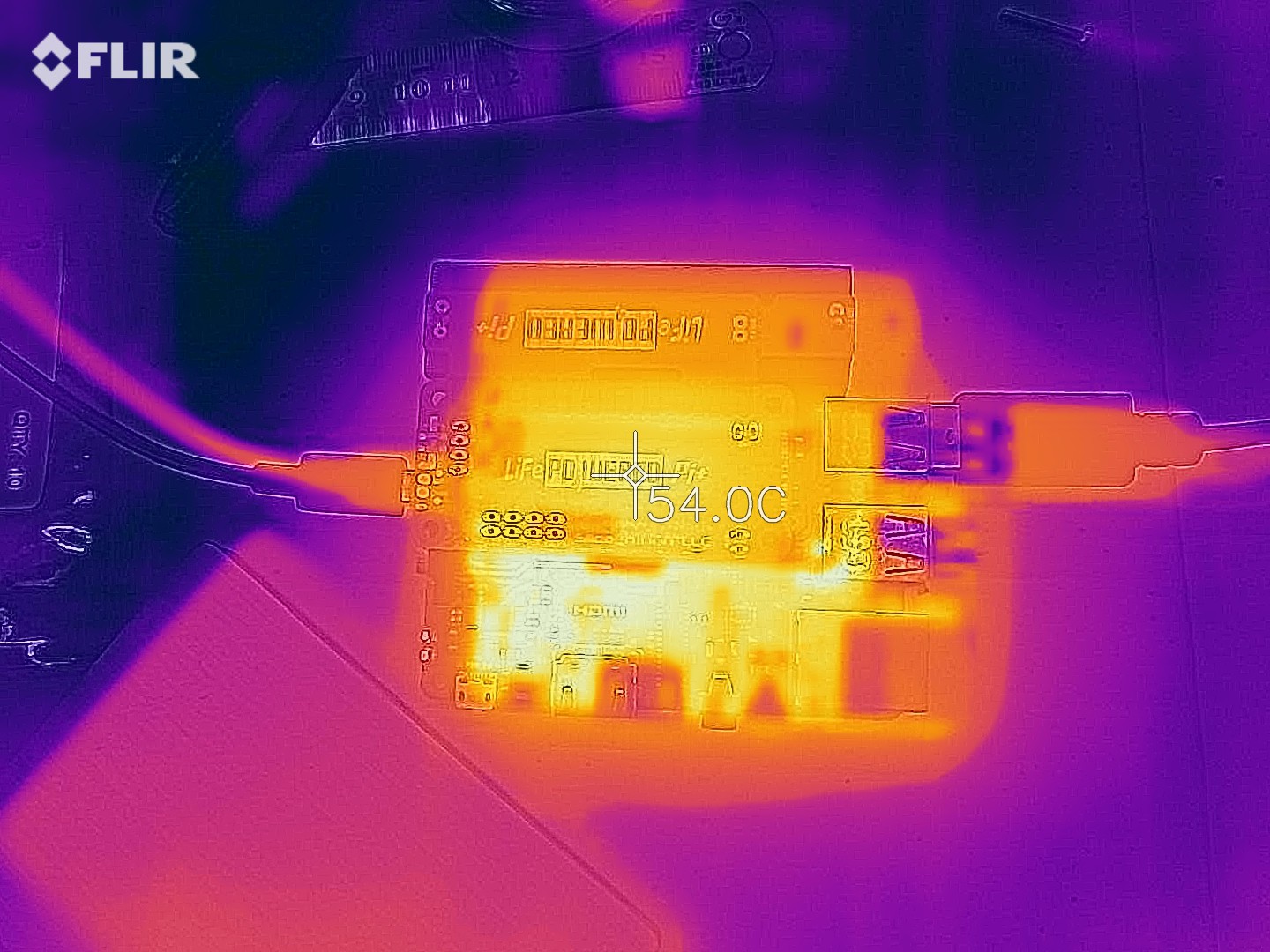
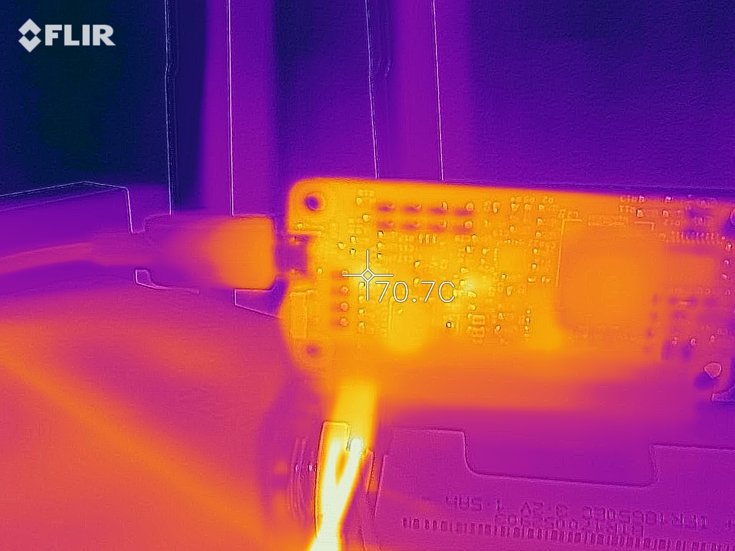
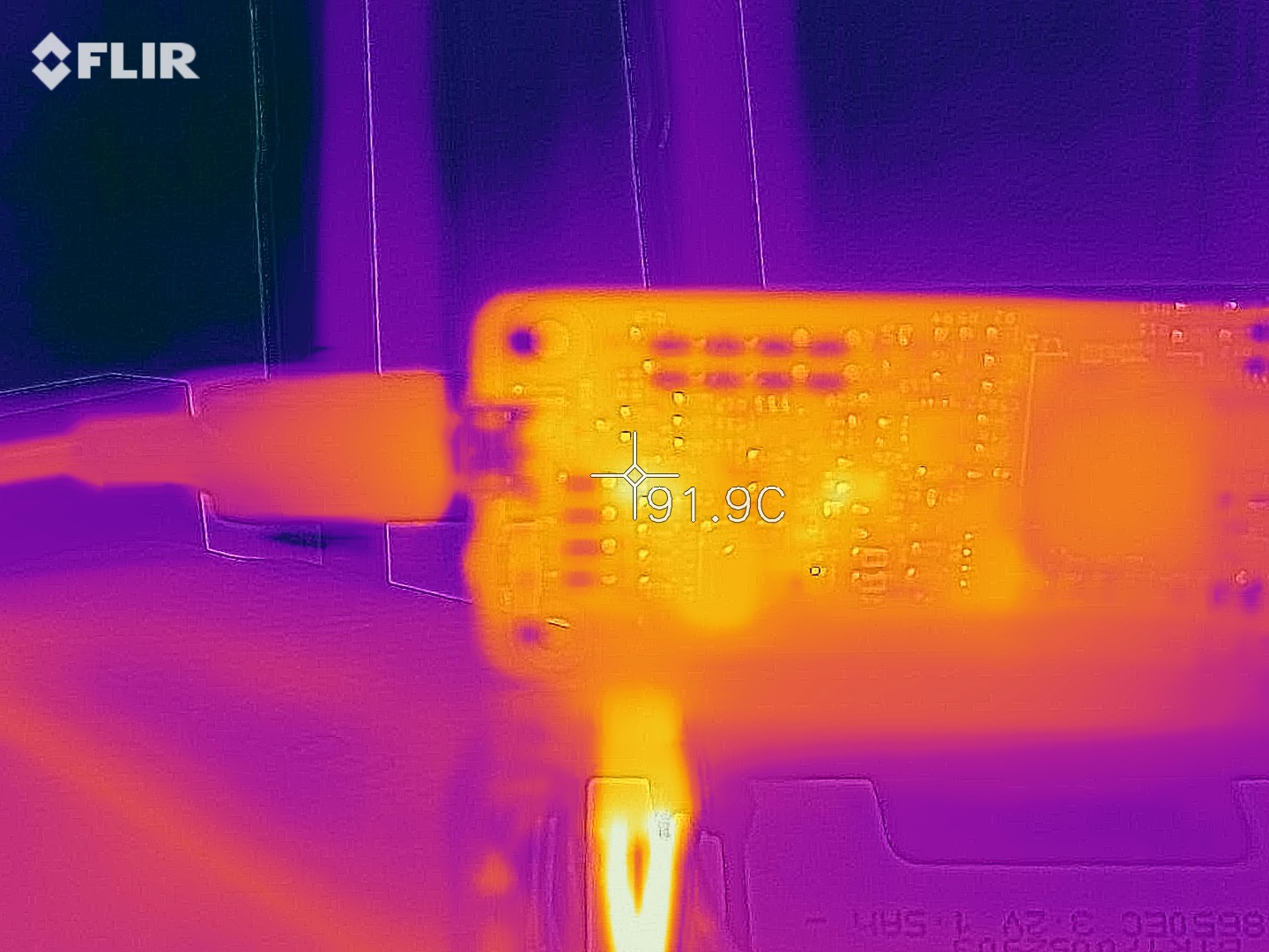
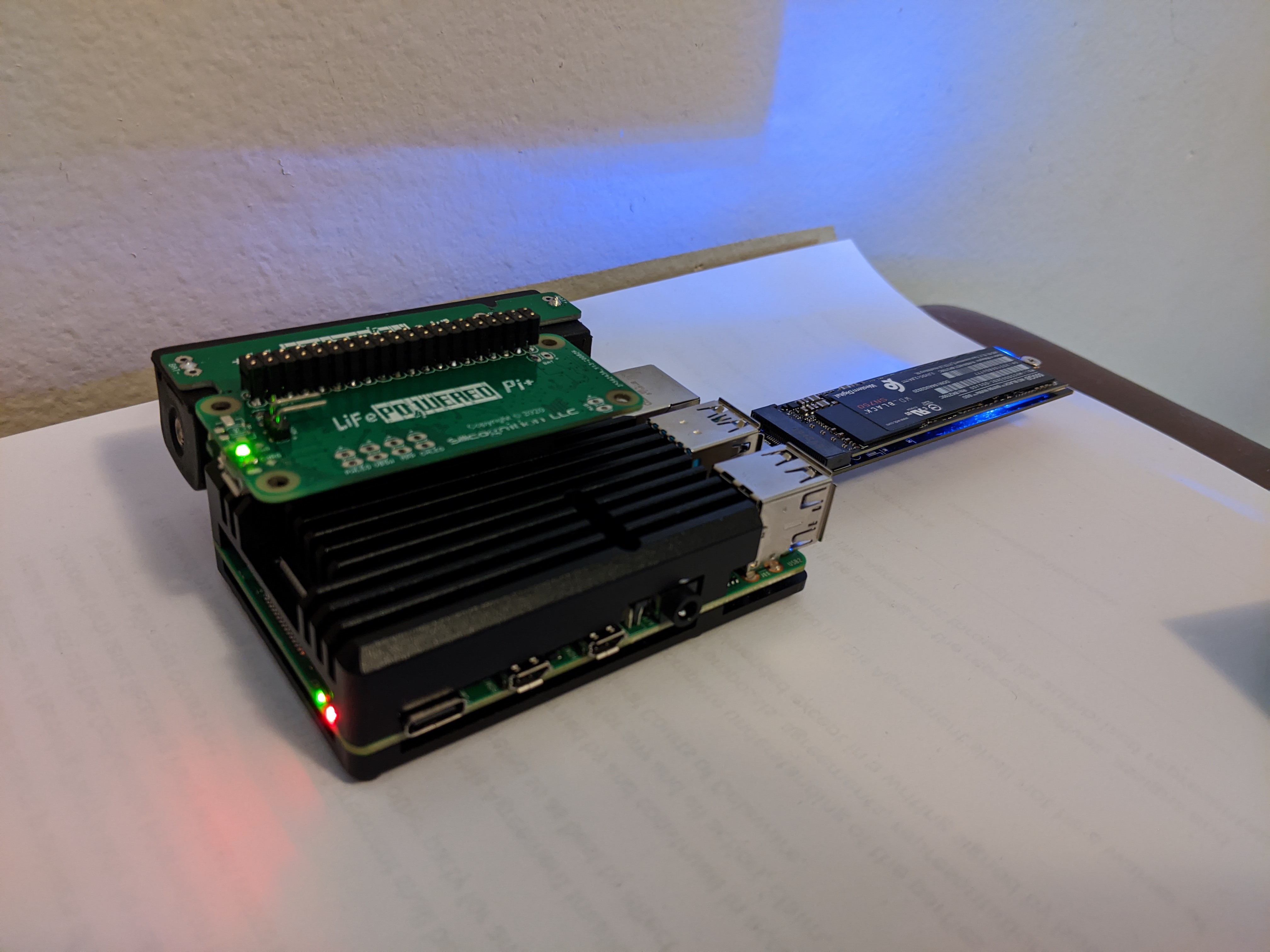 I wanted to make sure the system would run stable from both battery and when externally powered, and switch seamlessly between the two. I also wanted to take some thermal shots in both conditions.
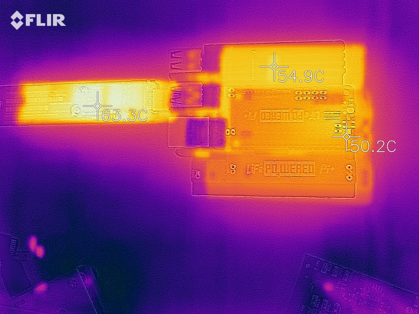 Sorry about the bad alignment between the thermal and optical in this image.
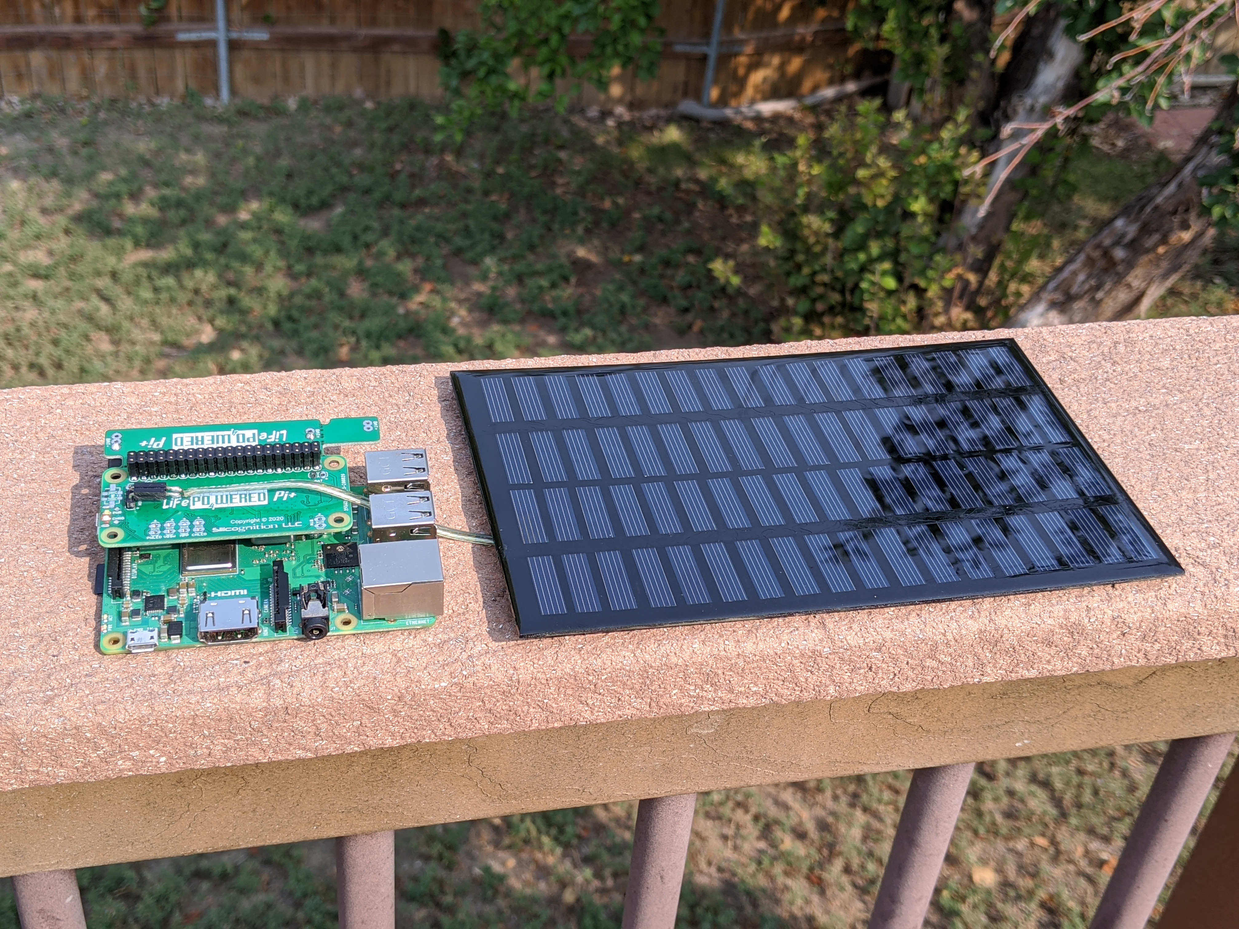
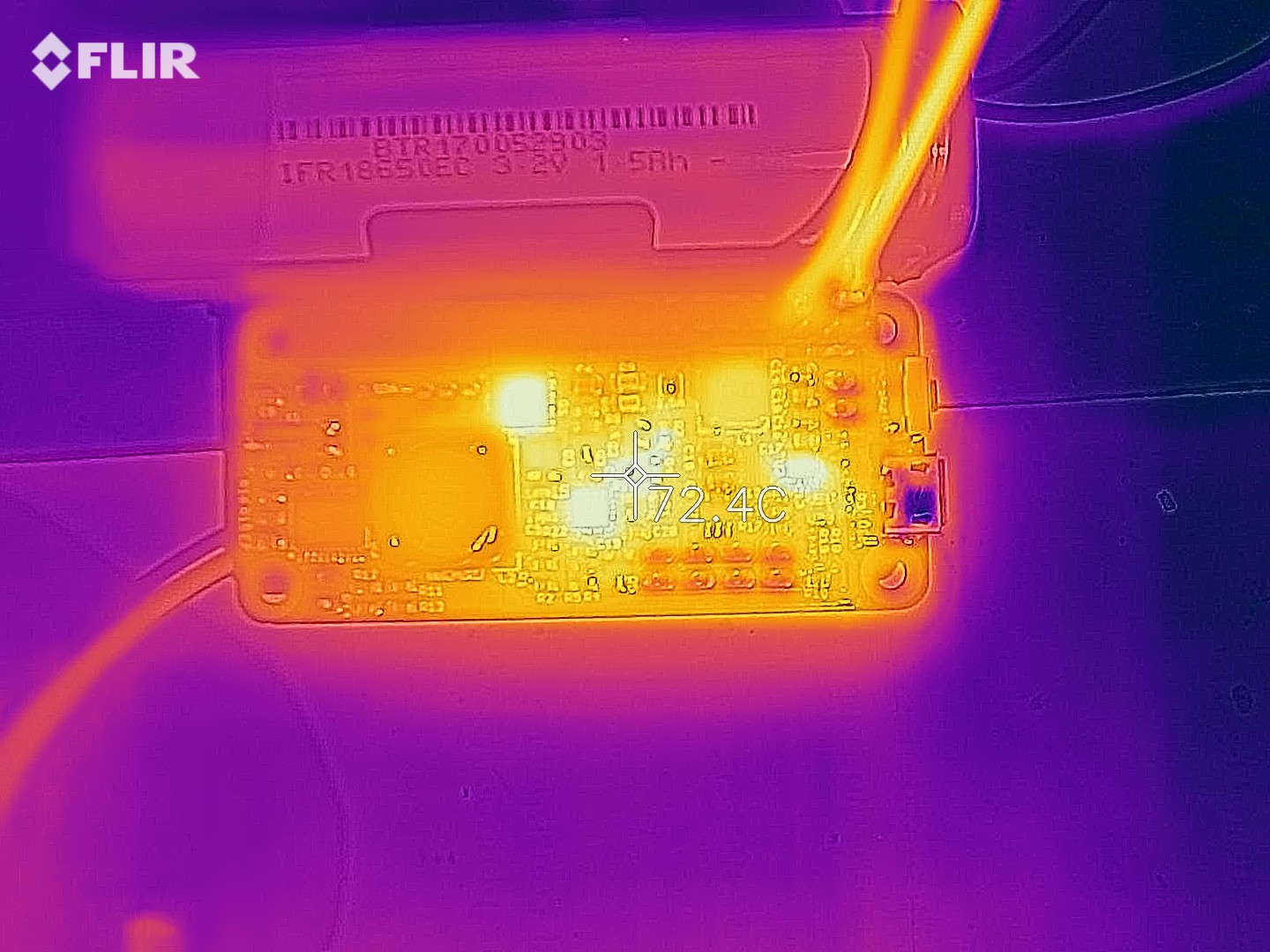
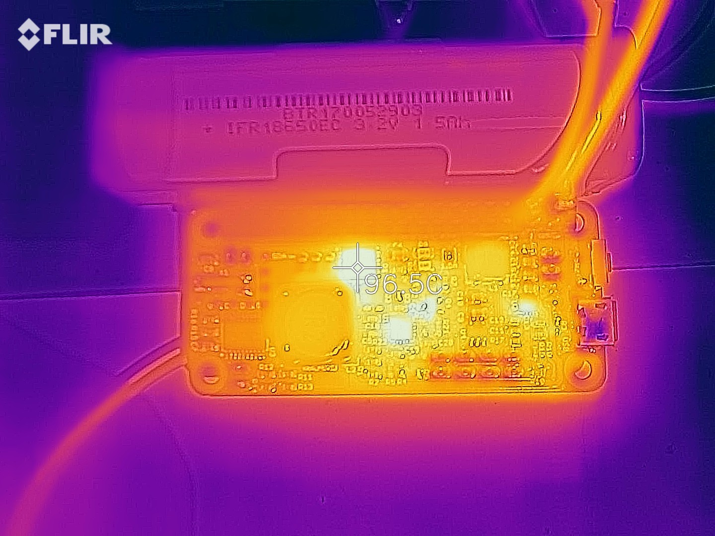
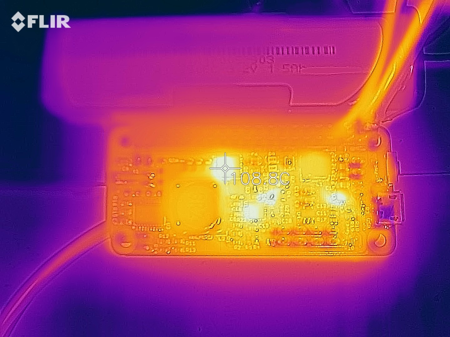
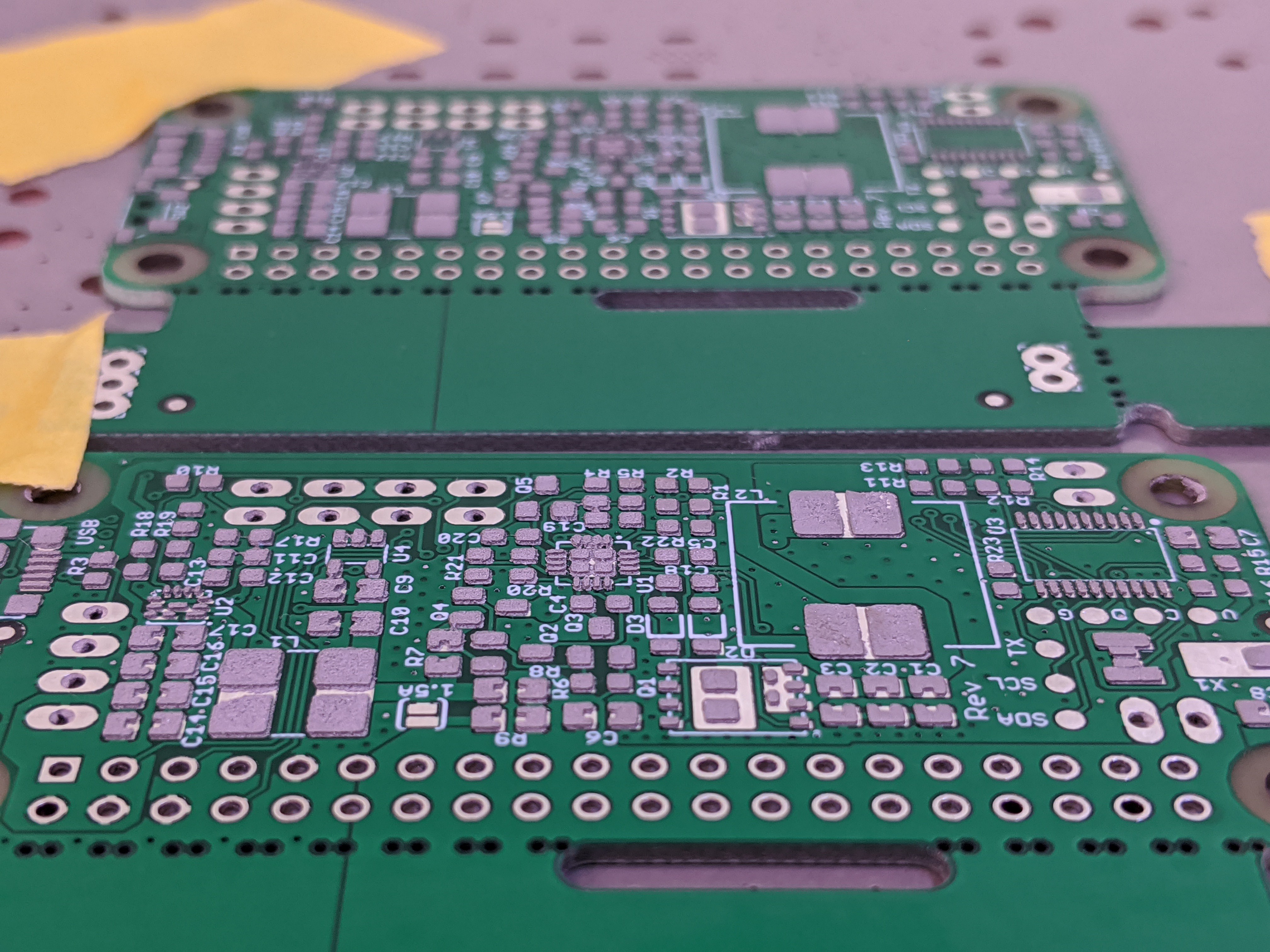
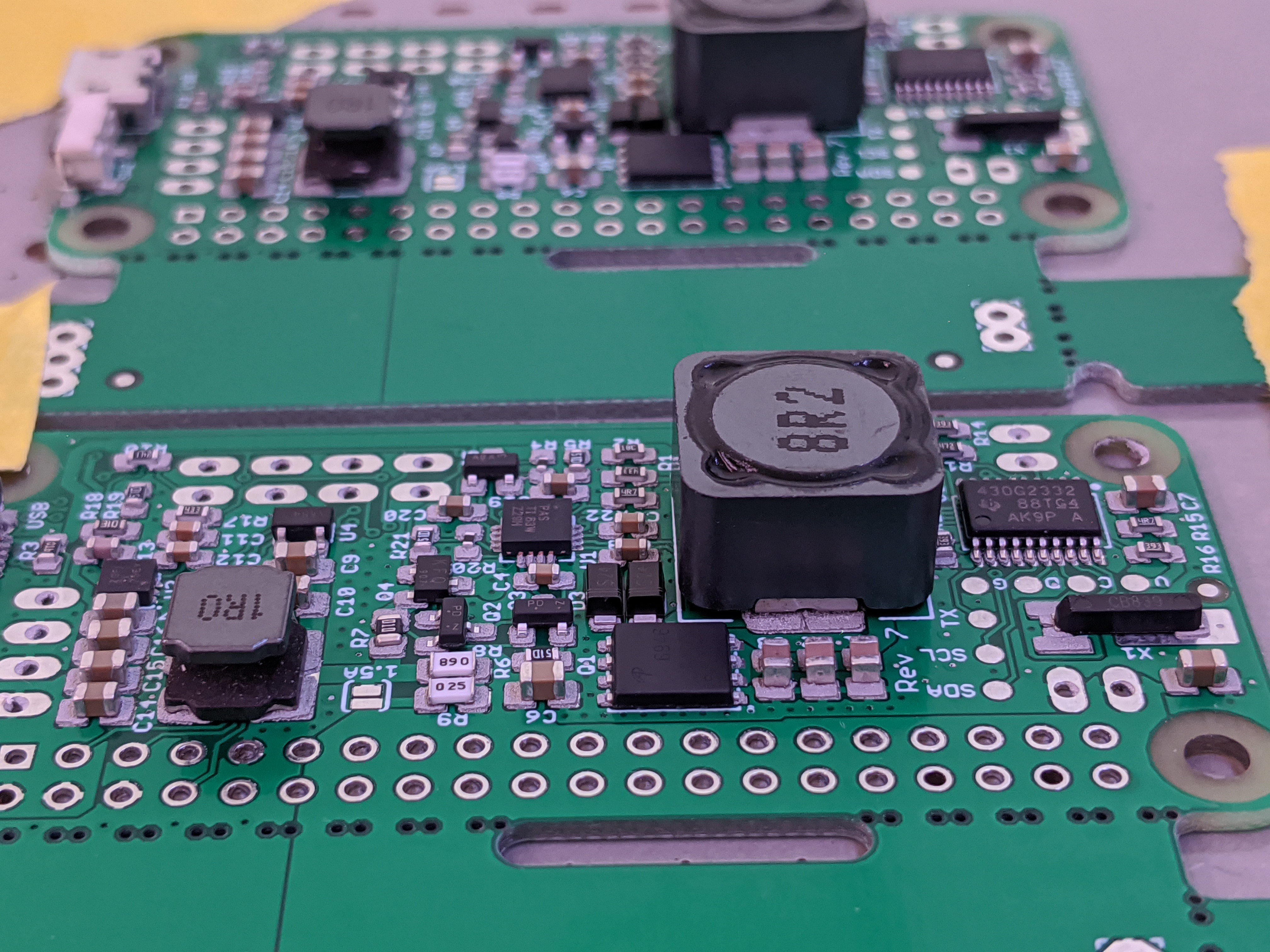
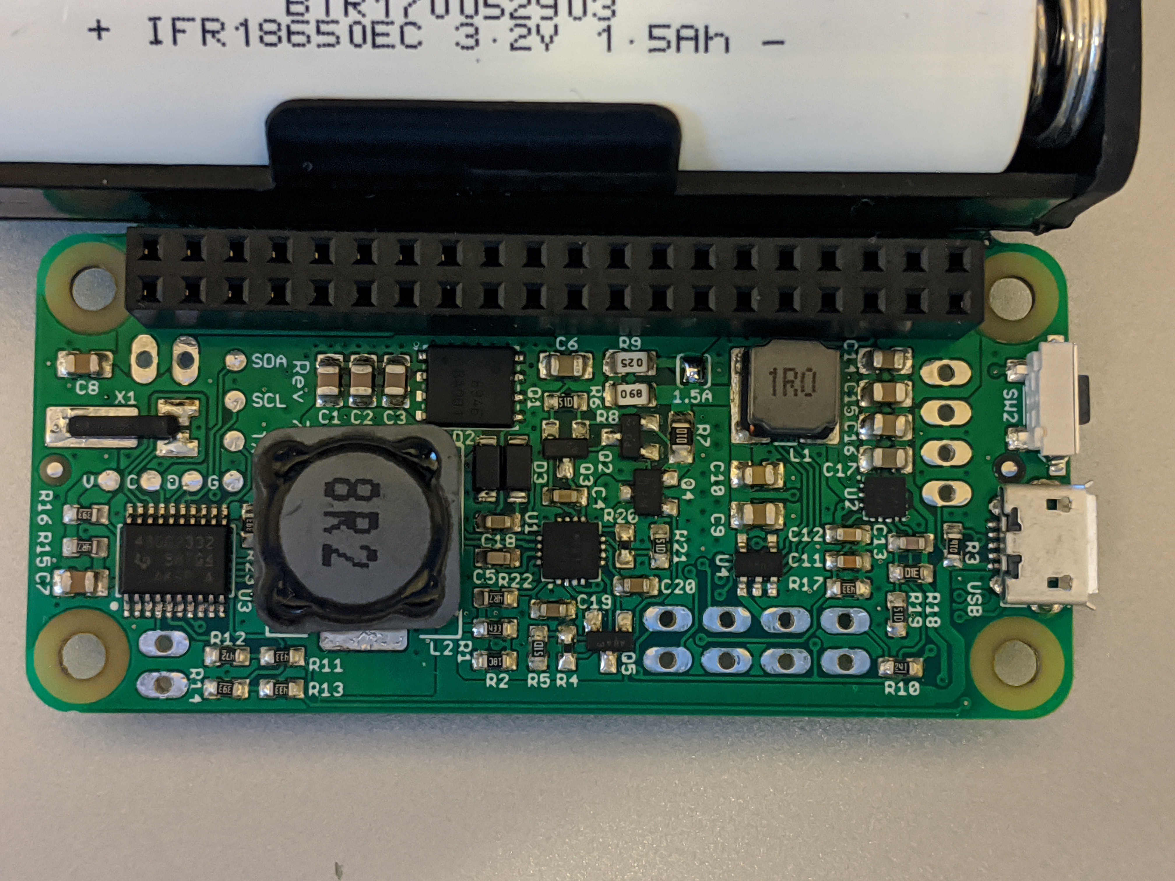
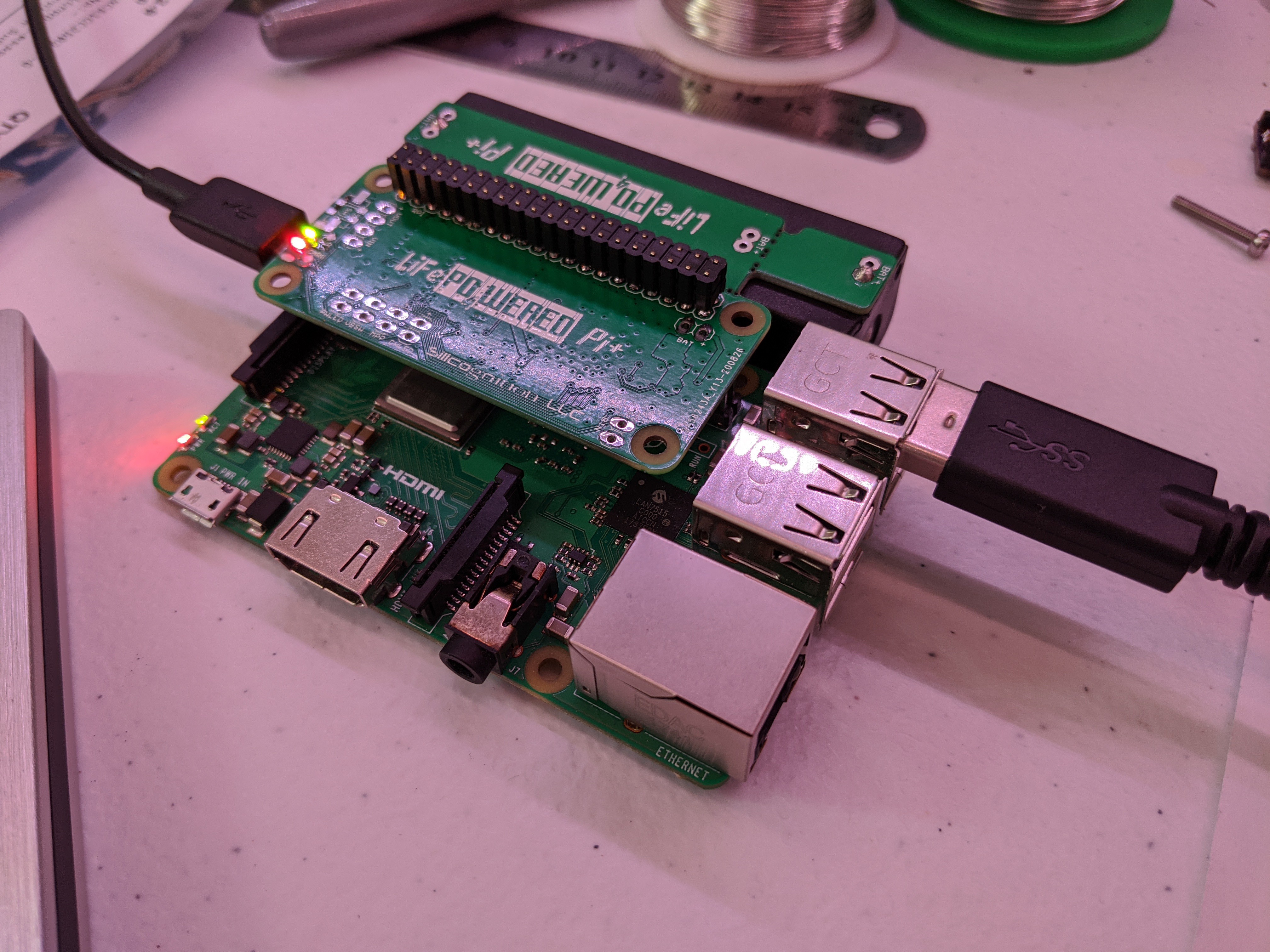
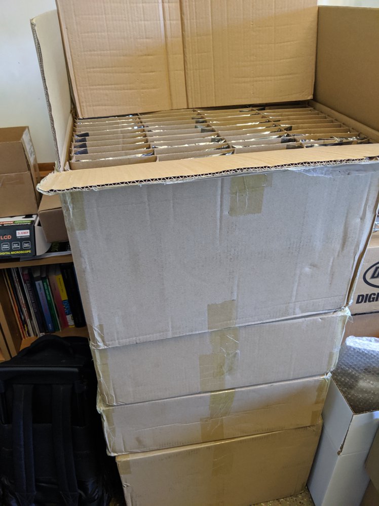
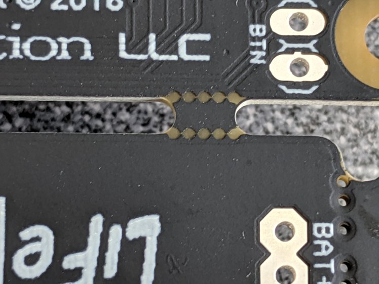
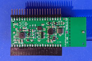
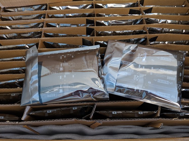 Very nicely packaged. And good quality product. I have not run into too many issues after testing and final assembly of several hundreds of these boards. I had one board that needed reflow of the TPS61236P boost converter. A couple of panels had this weird issue where the mouse bites to separate the boards weren’t all drilled:
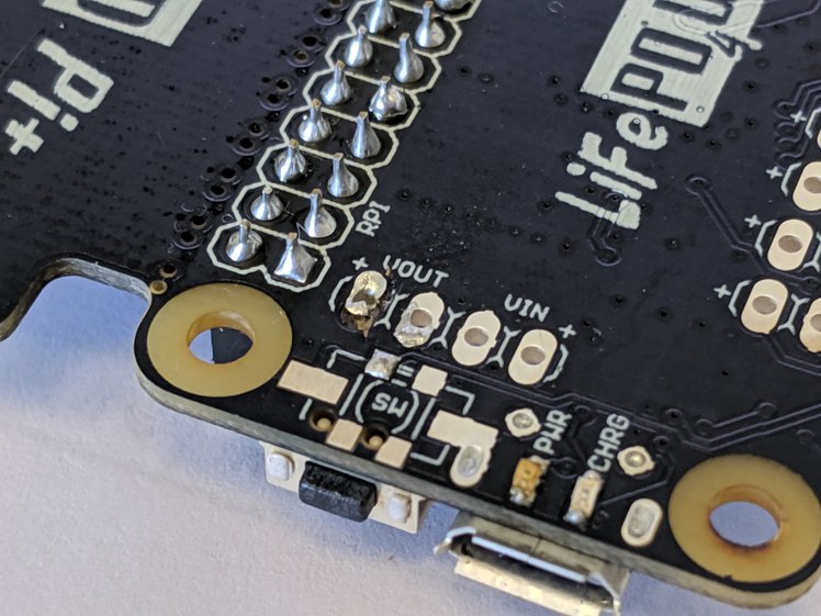
 And there was one board that had some cosmetic damage:
 But overall, production has been running smoothly. The
  Then came the time to put some load on it. I used the
 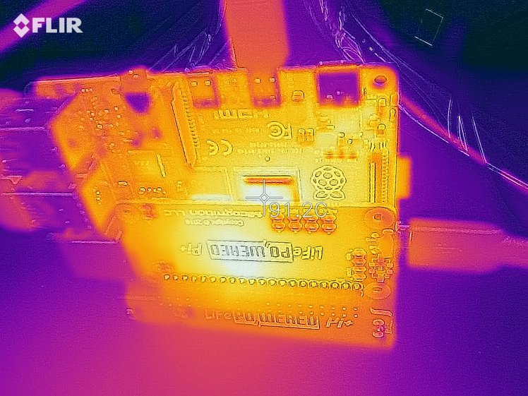 Both the Pi 4 CPU and the LiFePO4wered/Pi+ settled at a temperature of around 90˚C. When using a system like this at high load, it would obviously be wise to add cooling, but for testing, we like to abuse things. :)
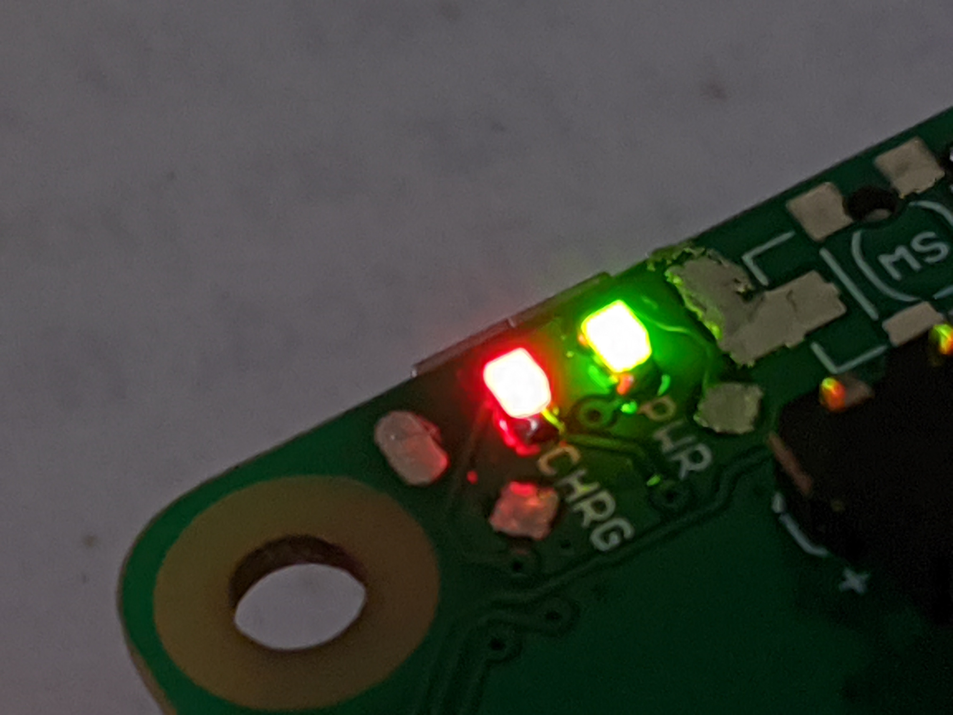
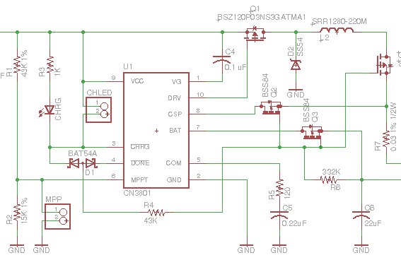 In all the LiFePO4wered/Pi3’s and the early LiFePO4wered/Pi+ batch I made, this always worked as expected. The CN3801 has an under voltage lockout at 3.8 V nominal, 3.1 V minimum, and my assumption and experience up till then was that this would keep the CHRG and DONE pins from turning on when the only voltage powering the CN3801 was battery voltage leaking back to this circuit through the diode drop of Q1’s body diode. The pass transistors would be turned off and the circuit would not leak back to the charge input.
 The circuit with zener diode and pre-biased transistor doesn’t depend on variations in the CN3801 anymore. Instead it depends on variations in the zener and transistor thresholds. Which can be just as problematic of course. But I think I’ve calculated the tolerances well enough to be pretty confident it will work as expected. Being based on a current driven device like an NPN transistor with pull-down on the base has the added benefit that it presents a bit more load than the purely MOSFET based circuitry I had before, which could more easily be turned on by small leakage currents.




 powerfeatherdev
 Bud Bennett
Just ordered one to try it out on my Pi5 with an AI NPU Hat also attached.