Close
0%
0%

Reversed transistor makes a discrete voltmeter

The MonoMeter is a discrete dual-slope integrating A/D, using a reversed NPN transistor as a stable reference

Similar projects worth following
0 followers
Nestled quietly on p.31 of TI's AN-74 "A Quad of Independently Functioning Comparators", is the unassuming remark that [...] any of National's process 21 transistors [...] can be used quite satisfactorily as a zero T.C zener. The app note goes on to describe how to use a reverse-biased transistor together with a comparator operated as a low-speed operational amplifier to provide a stable voltage supply (or four). This information has stuck around in my mind for many months now, and crystallized back to the fore when I discovered Hackaday's Component Abuse challenge. How perfect is it that, almost like an easter egg, TI (or National Semiconductor back in the day) encouraged misusing a transistor to obtain a stable voltage reference and then buffering it with a comparator no less! Armed with this, and a particular discrete rendition of a dual-slope integrating ADC with display, discovered when reverse-engineering a '70s densitometer, I hope to build a fun little voltmeter.

The concept

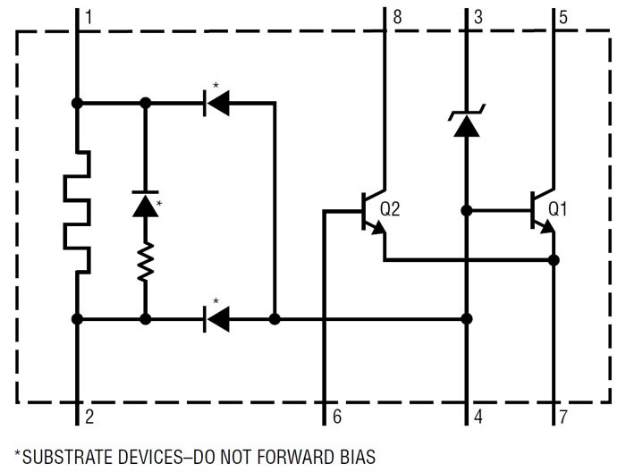
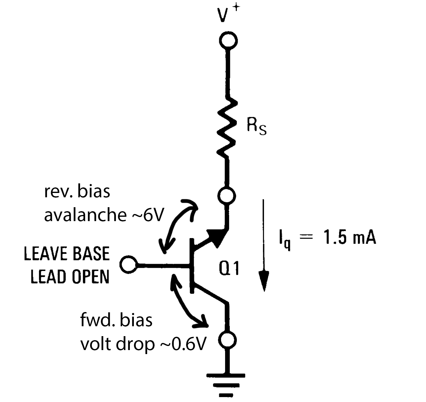
As I noted in the description, I am drawing on two inspirations in designing and constructing this project. The first is the almost offhand remark about using a reverse-biased c-e junction in an NPN transistor as a "zero temperature coefficient" zener diode. The other is a very basic, but elegant in my opinion, design for a dual-slope integrating ADC with display, used in the Macbeth TR-527 photographic densitometer.

To set some basic requirements for the device, I hope to successfully make a 3.5 digit voltmeter with a measuring range of 0.01-9.99 V, possibly bipolar, which uses 7-segment LED displays for indication. I would like to power it using a single 5 or 12V supply. At the heart of it will be a 10V reference, built using the aforementioned "abused" transistor as a zener diode, tweaked to as zero as a tempco as possible. 

In a more philosophical sense, I hope to blur the "Analog<>Digital" delineation, and in the spirit of the inspirational TI app note and the Hackaday challenge, I will try and use comparators instead of op-amps everywhere.

The plan

  • Obtain some "Process 21" NPN transistors, configure them as zeners, test temperature coefficient. Test some conventional transistors also (e.g. 2N3904, 2222 etc).
  • Design and built a reference circuit, which biases the "zener" with a constant current, buffers and amplifies the voltage to 10 V and feeds it to the A/D.
  • Design and build the A/D and display circuit using 74- or 4000-series logic and comparators, maybe an analog switch here or there.

  • Part 1: What's all this zero T.C. stuff, anyhow?

    Nikola2 days ago 0 comments

    To expand the T.I. quote

    Experimental data has shown that any of National's process 21 transistors
    which have been selected for low reverse beta (βR <.25) can be used quite satisfactorily as a zero T.C. Zener. When connected as shown in Figure 37, the T.C. of the base-emitter Zener voltage is exactly cancelled by the T.C. of the forward biased base-collector junction if biased at 1.5 mA.

    This makes a lot of sense. Zener diodes were among the first stable reference components used (preceded by neon gas-discharge tubes), and selected parts such as the 1N829 can achieve very low temperature coefficients when operated at the right current. Generally, zener diodes have a positive temperature coefficient of 1-2 mV/K, and this can be cancelled out neatly by the similar, but negative tempco of a normal PN junction, such as a silicon diode or the base-emitter junction in a bipolar transistor. This was quite common in linear discrete power supplies, and is the technique of choice for even the "highest precision" voltage reference ICs, such as the LTZ1000:

    Skipping over the components to the left, which form the basis of a very stable heater with feedback, Q1 and the zener diode on its base are used to derive the "ultrastable" low-noise reference voltage of about 7 volts. By tweaking the current through the zener and Q1, sub-ppm/K tempcos can be achieved.

    Bipolar transistors can be used as zeners, by reverse-biasing the E-B or C-B junctions. This is often used in clamp circuits, or other applications, where the exact voltage is not critical. The C-B junction, when reverse biased, will break down and avalanche anywhere from 15 to 1500 volts, depending on the transistor type. The E-B junction is "better-behaved" and almost always breaks down in the 5-6V region. And indeed, most often, when a BJT is used as a diode, forward-biased or as a zener, it is shown with the base and collector shorted, for example in this current source from Bob Widlar:

    However, in reviewing the structure of a BJT, it is evident that we are afforded two junctions, and fortuitously, we can reverse bias one and forward bias the other:

    The resulting sum has the fortuitous negation of the two temperature coefficients, and the potential to have a very low overall temperature dependence at the right current.

    Of course, a BJT is not intended to operate in this region, so we cannot expect the performance to match an LTZ1000, in terms of noise and ultimate stability. But, if we were looking to generate a voltage that is stable to a millivolt or so over a wide temperature range, a reversed bipolar seems like a good candidate.

    For what it's worth, there is not much information online about this configuration. I have only seen it officially suggested once, outside of AN-74, at the end of an application by Jim Williams in LT's AN9:

    Two NPN transistors here are used to derive the +/- 7V supply for an opamp from the available bipolar 15V rails.

    Process 21

    So, is there a secret to National's Process 21 that it would make better "zeners" than any other transistor? AN-74 explicitly states that the transistor should be selected for a low reverse beta. In my mind, the lower the reverse beta (i.e. the current gain when the emitter voltage is higher than the collector voltage, as would be in the zener configuration), the closer the BJT approximates two discrete diodes in series. Another clue comes from the die image in the National Transistor Databook:

    These are nominally RF switching transistors, used in high-speed applications at relatively low voltages, which would be a hint when I look for purchaseable equivalents.

    But for now, let's test one.

View project log

Enjoy this project?

Share

Discussions

Similar Projects

Does this project spark your interest?

Become a member to follow this project and never miss any updates