 Vitaly Kornilov
USB-OV2640-module
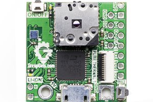
Compact USB camera module based on ESP32-S3 with directly soldered OV2640 sensor (BGA footprint).
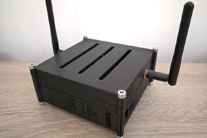
Conceptually close to ESP32-CAM, but implemented in a USB stick form factor with integrated antenna and memory.
Designed as a flexible platform that can later be adapted to other sensors and microcontrollers.

What’s on the board
- ESP32-S3 microcontroller
- Native DVP camera interface for OV2640
- USB 2.0 device controller (Type-C connector)
- OV2640 camera sensor in BGA package (soldered directly)
- Data lines matched in length with pixel clock
- Pin mapping (see table below)
- External memories:
- W25Q64JVSSIQ (SPI NOR Flash, 64 Mbit)
- LY68L6400SLIT (PSRAM, 64 Mbit)
- PCB antenna
- LC matching network (tunable if needed)
- Power & protection:
- ESD protection on USB data and power
- Small differential USB filter
- Debug & programming:
- BOOT and RESET buttons
- UART broken out for flashing/debug
- Extra GPIOs exposed (see table below)
- JTAG pads (MTCK, MTDO, MTDI, MTMS)
Pinout (ESP32-S3 ↔ OV2640)
| ESP32-S3 GPIO | OV2640 Signal | Notes |
|---|---|---|
| GPIO1 | Y9 | Data bus |
| GPIO2 | Y8 | Data bus |
| GPIO3 | Y7 | Data bus |
| GPIO4 | Y6 | Data bus |
| GPIO5 | Y5 | Data bus |
| GPIO6 | Y4 | Data bus |
| GPIO7 | Y3 | Data bus |
| GPIO8 | Y2 | Data bus |
| GPIO9 | PCLK | Pixel clock |
| GPIO10 | XVCLK | External clock |
| GPIO11 | HREF | Horizontal reference |
| GPIO12 | VSYNC | Vertical sync |
| GPIO13 | RESETB | Sensor reset |
| GPIO18 | SIO_C | SCCB/I²C clock |
| GPIO17 | SIO_D | SCCB/I²C data |
| GPIO14 | STROBE | Camera strobe |
| GPIO38 | FREX | Frame exposure |
| GPIO37 | EXPST_B | Exposure start |
Extra Exposed GPIOs
| GPIO | Possible Functions (ESP32-S3 datasheet) |
|---|---|
| GPIO33 | ADC1_CH2 • Touch5 • RMT • SPI • UART • PWM |
| GPIO34 | ADC1_CH3 • Touch6 • RMT • SPI • UART • PWM |
| GPIO35 | ADC1_CH4 • Touch7 • RMT • SPI • UART • PWM |
| GPIO36 | ADC1_CH5 • Touch8 • RMT • SPI • UART • PWM |
| GPIO45 | General-purpose IO (no ADC/touch) • HSPI/VSPI • PWM • UART |
| GPIO46 | Input-only • Strapping pin • Can be used as input for boot mode, JTAG, etc. |
| GPIO21 | ADC2_CH0 • Touch0 • I²C SDA • UART • PWM |
| GPIO15 | ADC2_CH4 • Touch3 • I²C SCL • UART • PWM |
| GPIO16 | ADC2_CH5 • Touch4 • SPI • UART • PWM |
Notes:
- ADC1 and ADC2 allow analog measurements (12-bit).
- TouchX functions support capacitive touch sensing.
- RMT = Remote Control peripheral (good for IR / precise waveforms).
- GPIO45/46 often used in special boot/JTAG scenarios — check strapping requirements.
- All can be remapped to UART / I²C / SPI / PWM as needed (ESP32-S3 flexible IO matrix).
Power & Form Factor
- Powered directly from USB Type-C
- Compact 2-layer PCB for low-cost manufacturing
- No external power required
Use Case
- Drop-in USB camera module with OV2640 sensor
- Alternative to ESP32-CAM with direct USB interface
- For prototyping, computer vision, robotics, and IoT devices
Quick Use
- Connect USB-OV2640-module to PC via USB-C.
- Hold BOOT and press RESET to enter download mode.
- Flash ESP32-S3 firmware (e.g. ESP-IDF / Arduino / PlatformIO).
- Use provided OV2640 driver examples (similar to ESP32-CAM).
- Stream video over USB (UVC emulation) or Wi-Fi.
Notes
- Antenna may require LC matching calibration depending on PCB batch.
- OV2640 mounted directly in BGA footprint (reflow soldering required).
- Camera lines length-matched for stable operation at full pixel clock.
- PCB made as 2-layer design for cost efficiency.
 Pure Engineering
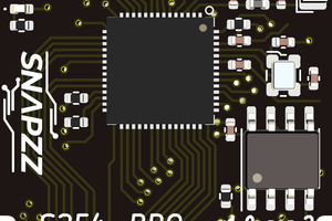
 Thorsten Jaeger
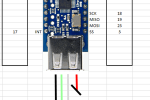
 drcyberg