 Daniel Knezevic
Introduction
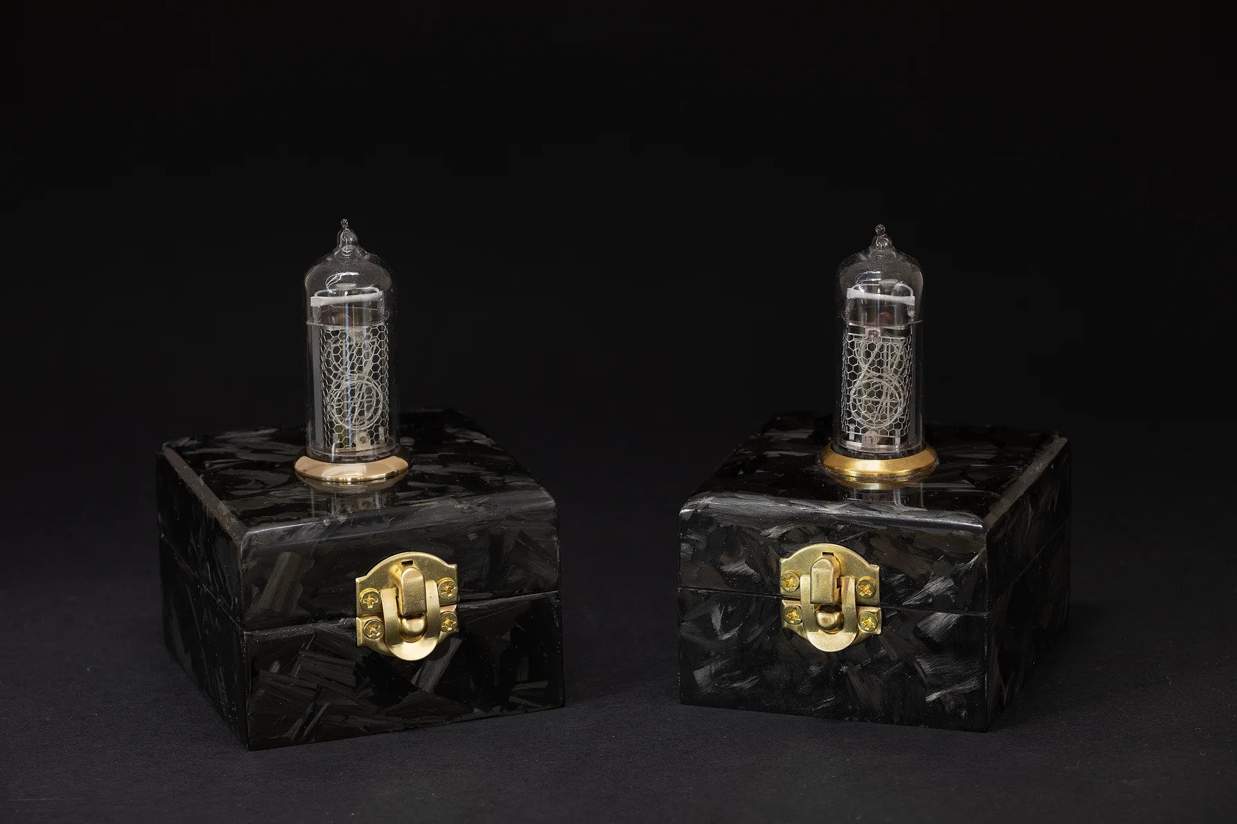
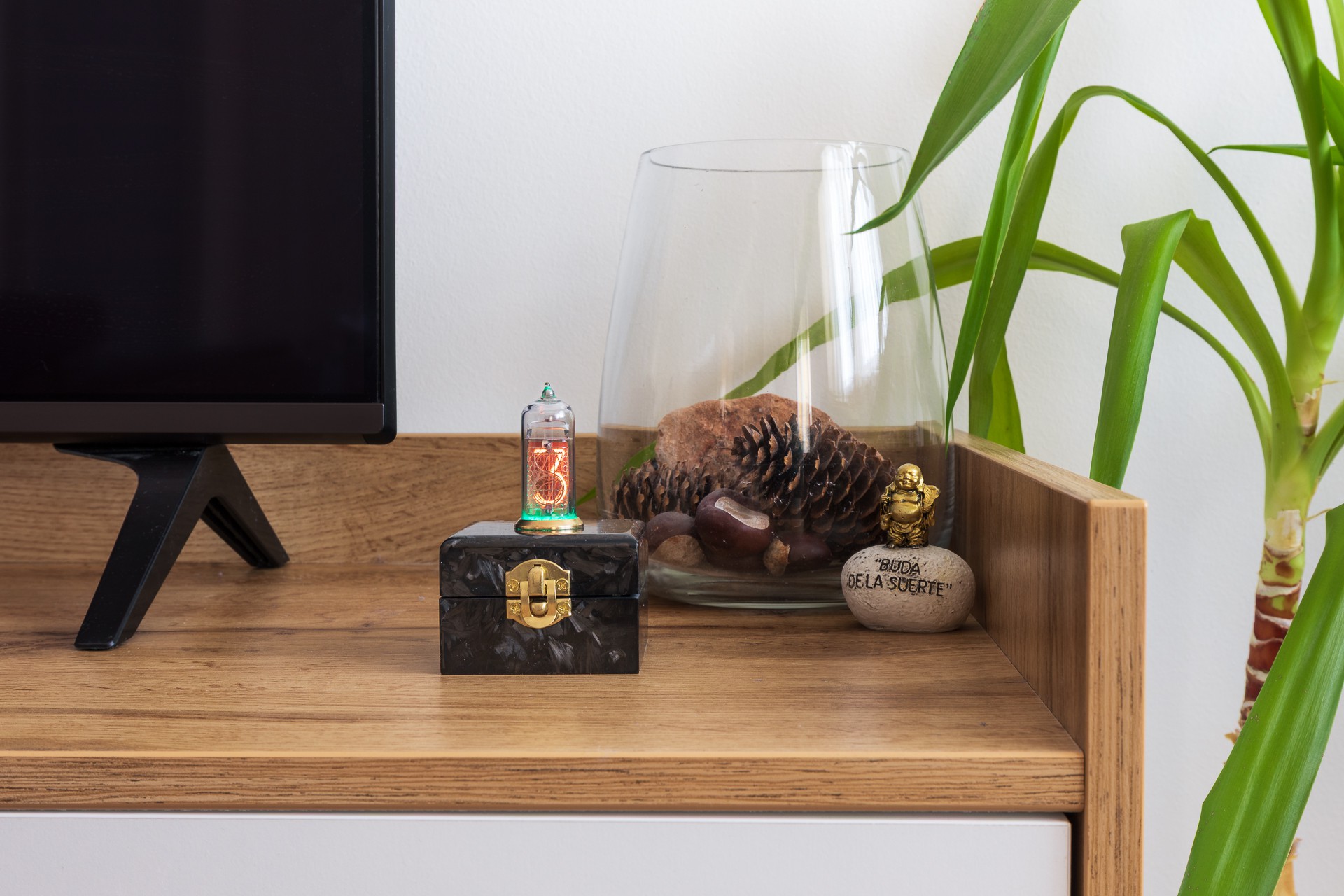
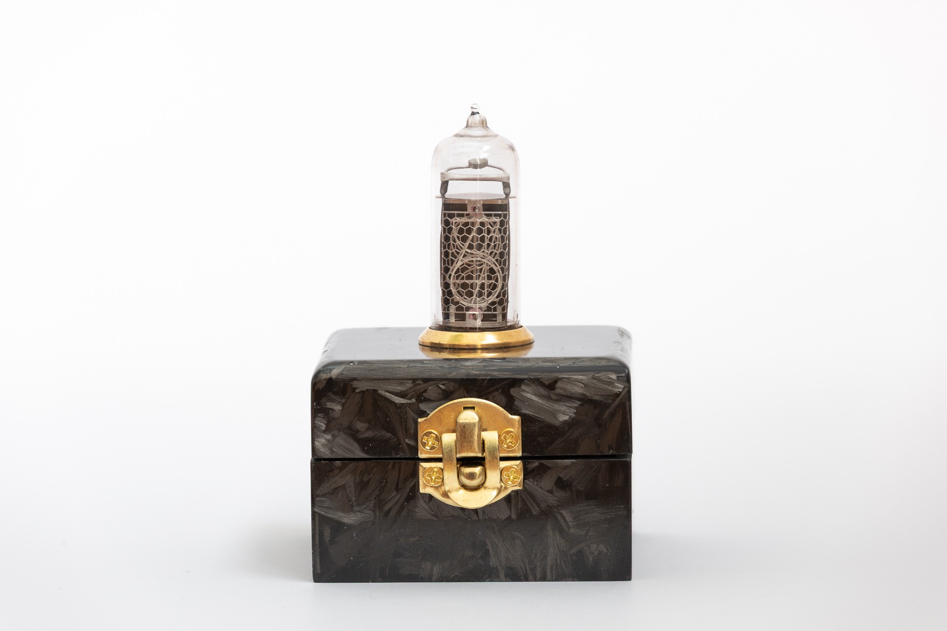
I’ve always been fascinated by Nixie tubes. There is something special in them. Probably their shape, analog feel and the glowing numbers are making these tubes standing out from the new, more modern counterparts. Couple of years ago I bought a couple of IN-14 nixie tubes from AliExpress. To be more precise 3 of them.
It was easy to decide what to use these tubes for: clock. Yes, yet another implementation of a Nixie clock. A bit boring, I know, I know… But, I wanted to implement my own version of it.
As you may know, at least 4 tubes are needed for a clock to show time in format like HH:MM. So, I had two options: order one more tube or come up with something different. Since nixie tubes are not on the cheap side I decided to use only one tube for a clock.
List of requirements
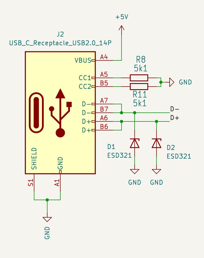
- Power the clock from USB
- Store time on a Real-Time-Clock
- Interface the clock via Wireless
Details
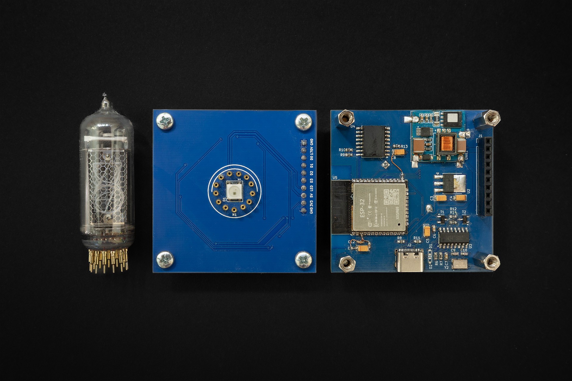
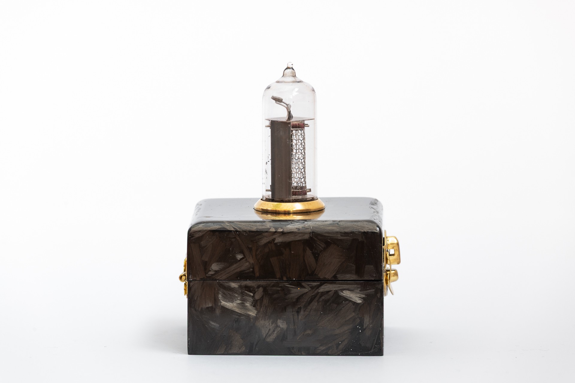
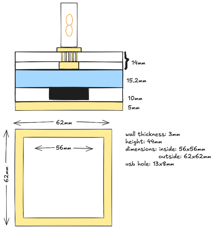
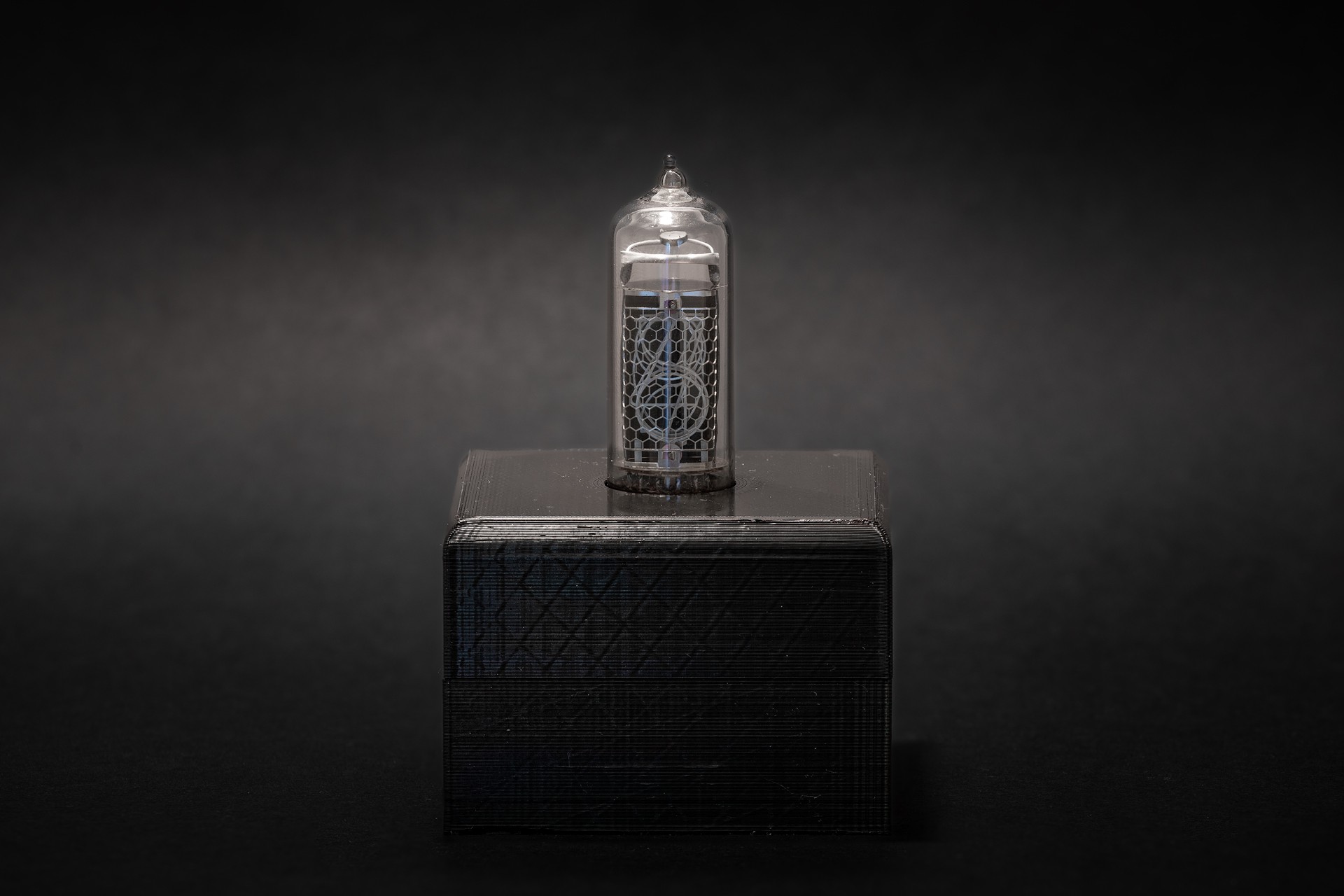
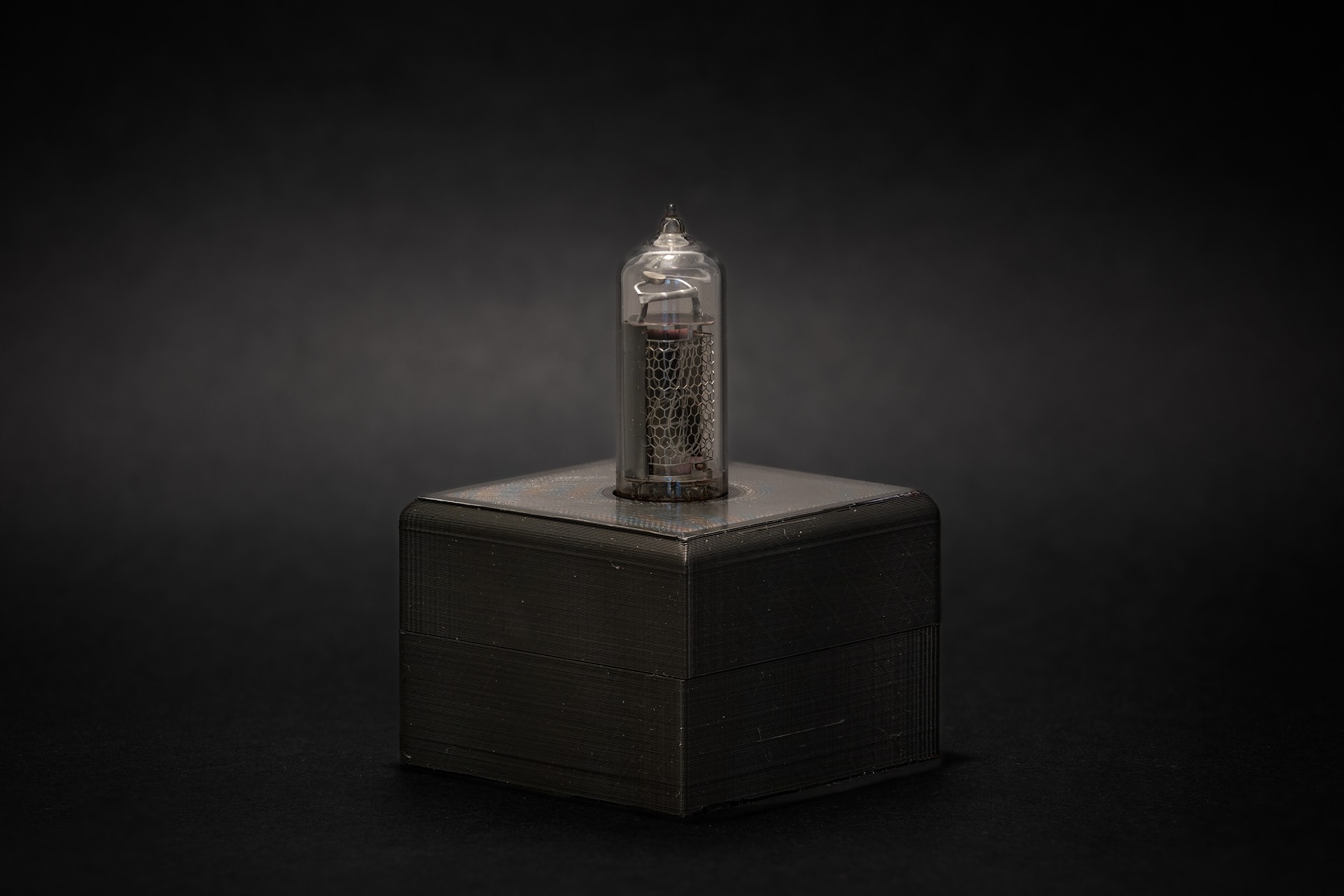
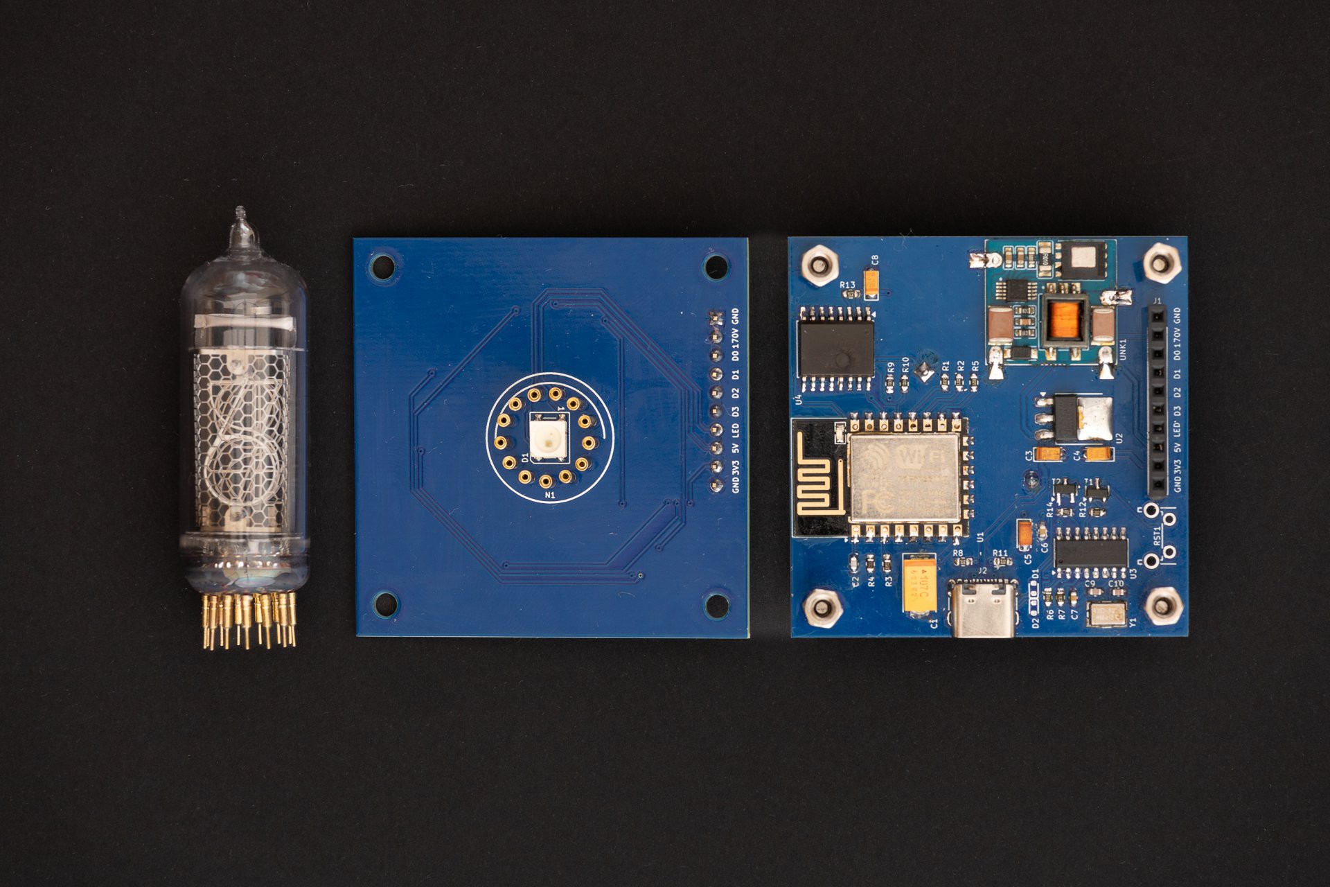
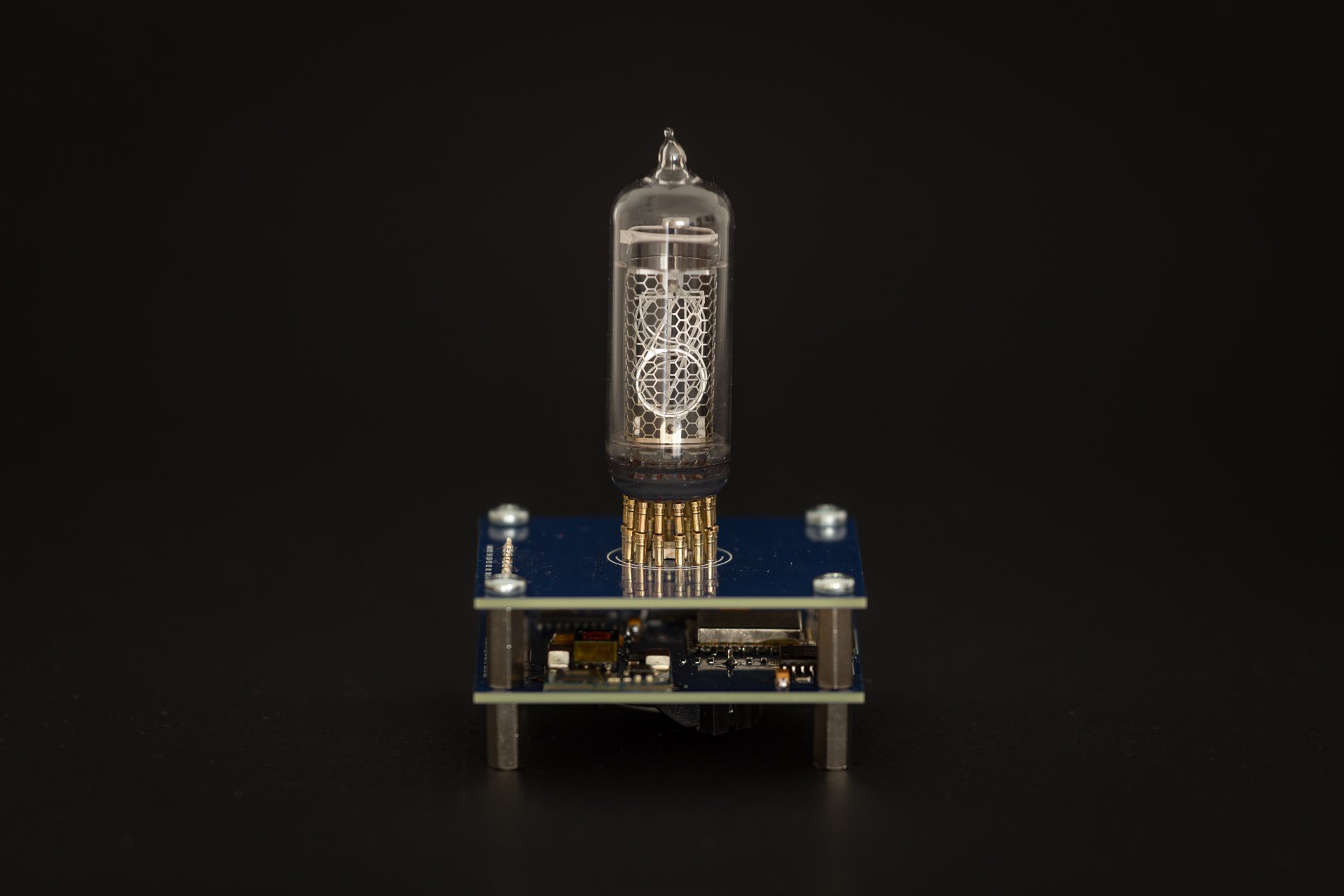
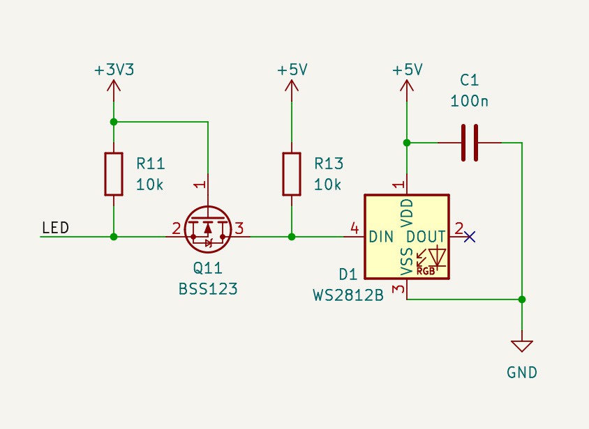
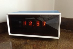
The end product is a stack of 2 PCBs where the bottom one is the control board containing the ESP with Nixie supply and the top one is the display board containing the RGB LED and the Nixie tube.
Operating modes:
- AP mode
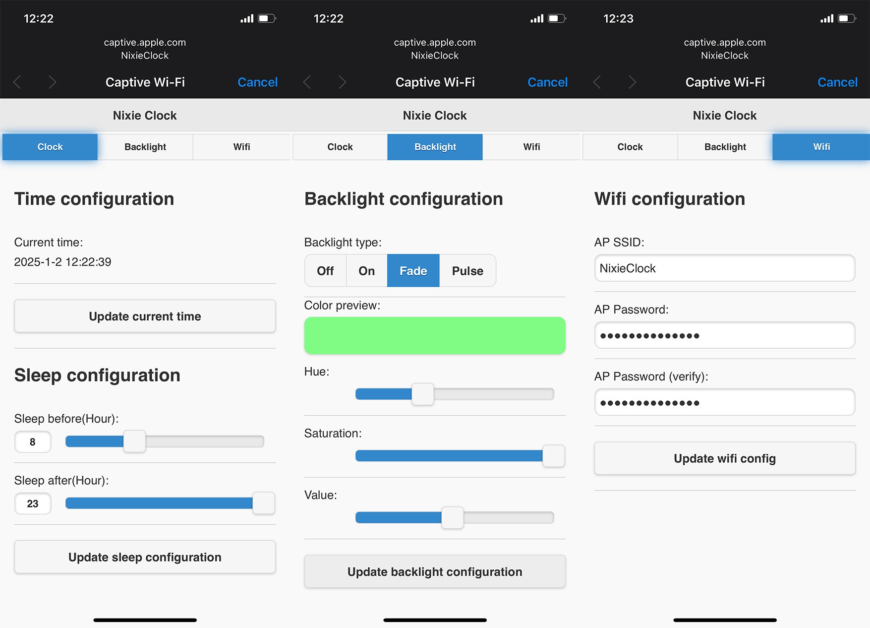
- This mode is hosting a dedicated open wifi network called NixieClock. Its main purpose is to use it for first time setup to update wifi configuration. In addition, this mode will be activated when the clock is not able to connect to a configured network. Clock hosts a captive portal. A configuration page will be opened automatically upon connecting to `NixieClock` network.
- Client mode
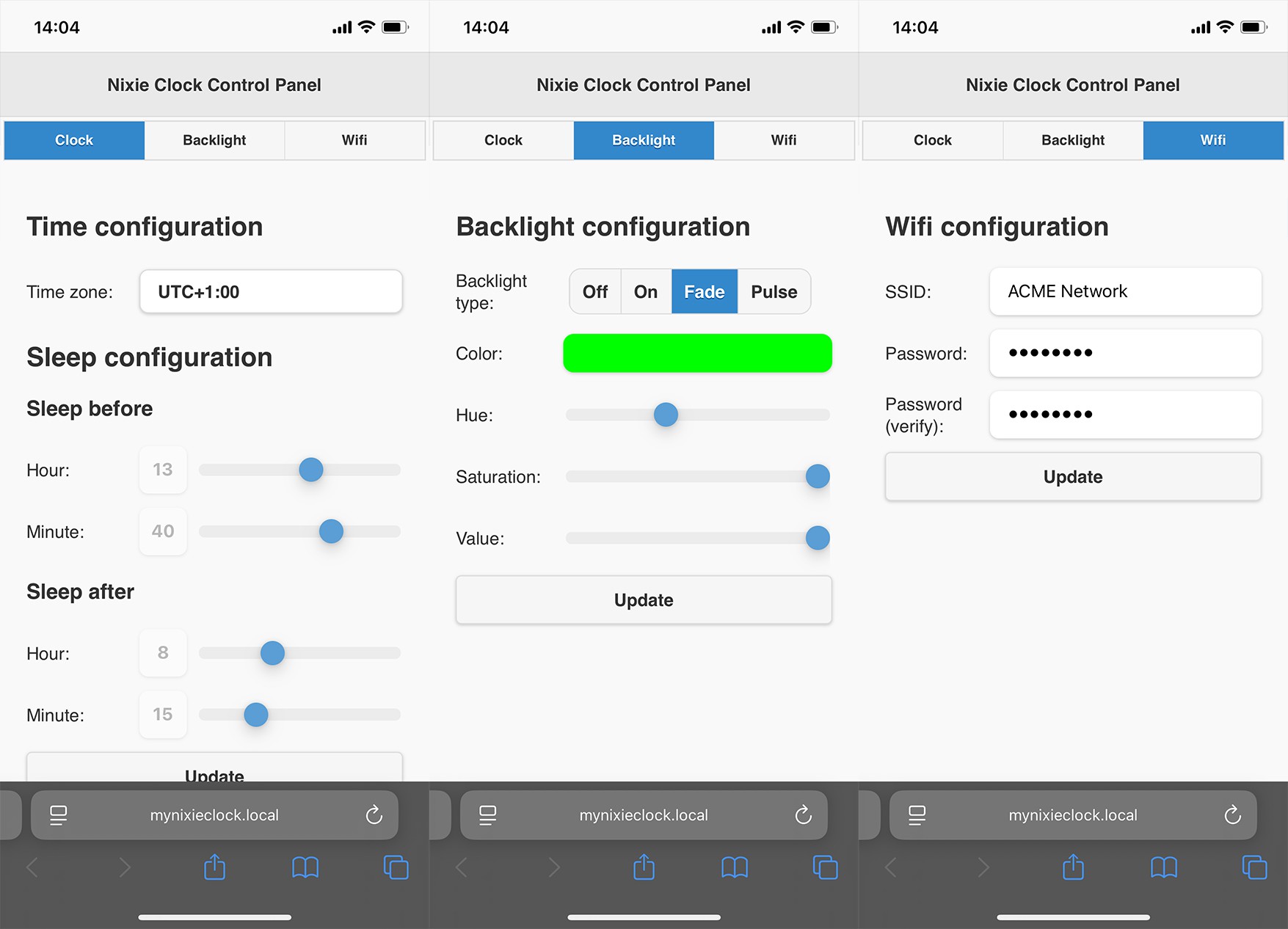
- In this mode the clock is connected to a configured wifi network. If there is internet access, the clock will synchronize its RTC with NTP server at startup and then every hour periodically.
In both modes, the configuration page is easily reachable on the following URL: mynixieclock.local. There is no need to keep track of the IP address, the clock is hosting Multicast DNS (mDNS) server. mDNS is supported by Chrome and Safari browsers out of the box.
Short demo:
Note: The demo is without the Wifi tab.
Firmware
This project started on ESP8266 with the Arduino framework, which was great for fast prototyping. However, the reliance on third-party libraries often led to instability and crashes.
To ensure long-term support and stability, the project was migrated from the now-obsolete ESP8266 to the ESP32, using ESP-IDF in C++.
This move provides:
- A robust and stable firmware base.
- Full access to ESP32’s hardware features.
- Use of official ESP-IDF components
REST API
| End point | Method | Body (JSON) | Description |
| /api/v1/led/led_info | GET | { “R”: <0-255>, “G”: <0-255>, “B”: <0-255>, “state”: <0-2> } | Get color and state of the backlight (RGB LED). |
| /api/v1/led/led_info | POST | {
“R”: <0-255>, “G”: <0-255>, “B”: <0-255>, “state”: <0-2> } | Set color and state of the backlight (RGB LED). |
| /api/v1/clock/time_info | GET | { "tz_zone": "<Geographic zone>", “tz_offset”: “<Proleptic TZ>", "time_format": <"12h" | "24h"> } | Get time zone configuration |
| /api/v1/clock/time_info | POST | { "tz_zone": "<Geographic zone>", “tz_offset”: “<Proleptic TZ>", "time_format": <"12h" | "24h"> } | Set time zone configuration |
| /api/v1/clock/sleep_info | GET | { “sleep_before”: <value>, “sleep_after”: <value> } | Get sleep mode configuration. The time before and after (in minutes) the backlight will be turned off. |
| /api/v1/clock/sleep_info | POST | { “sleep_before”: <0-23>, “sleep_after”:... |


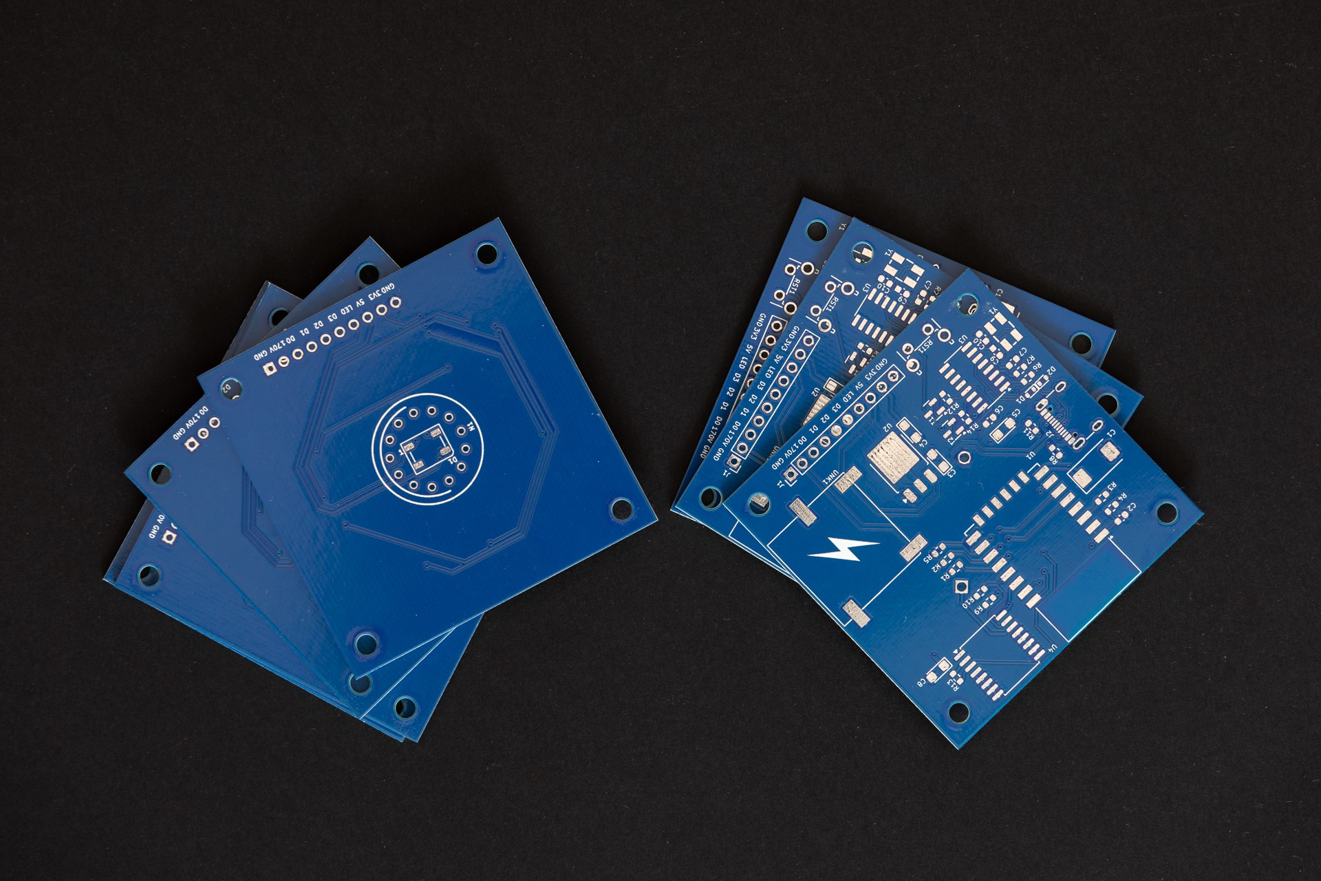
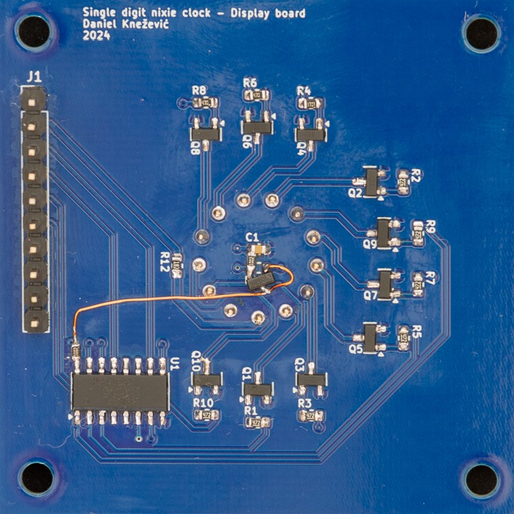
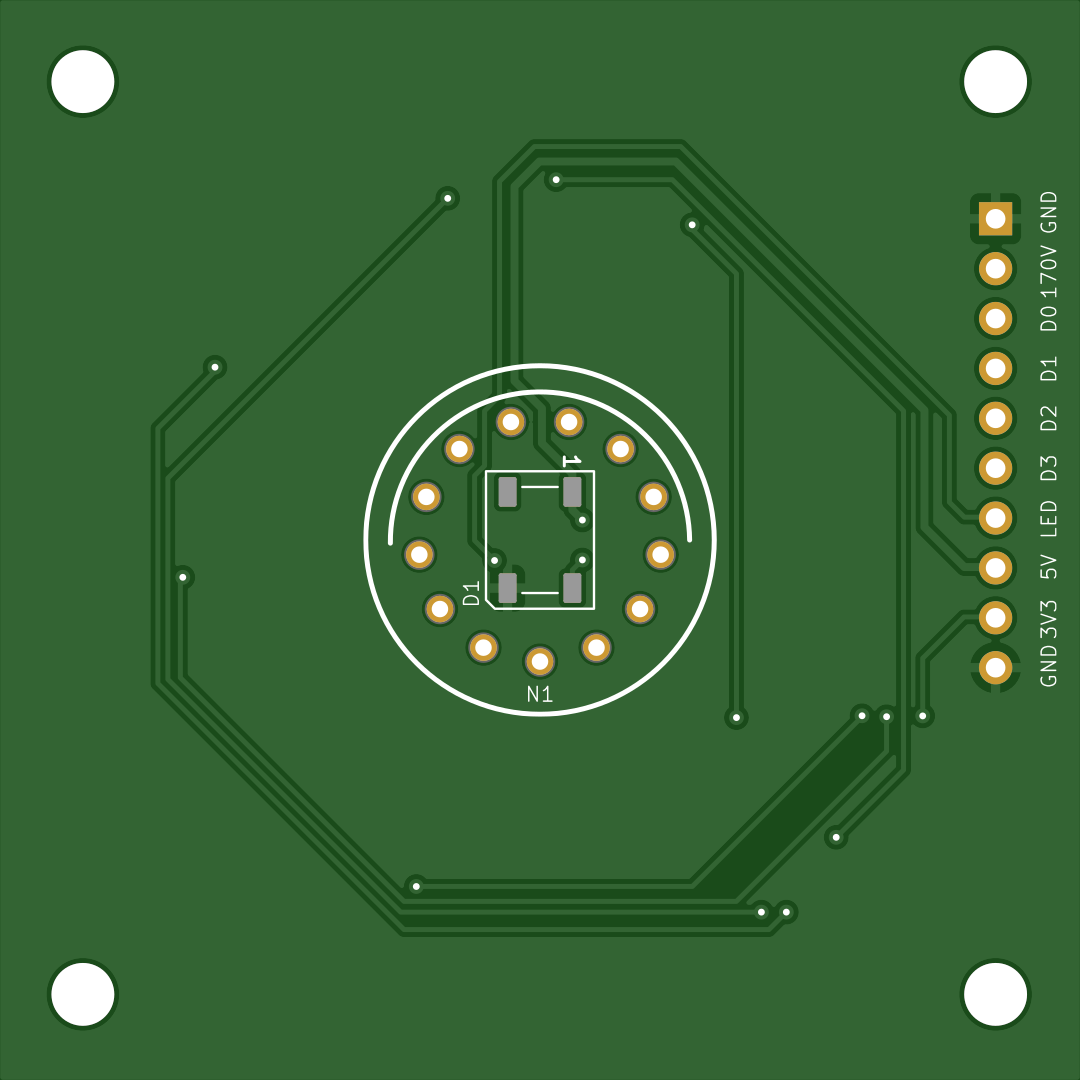
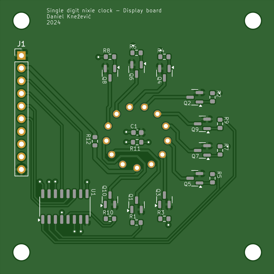
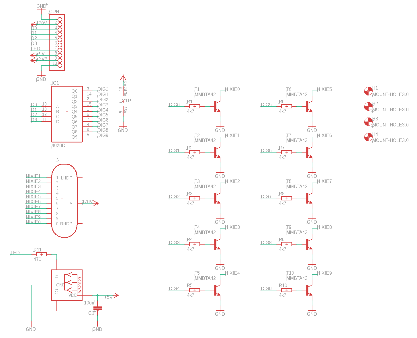 PCB
PCB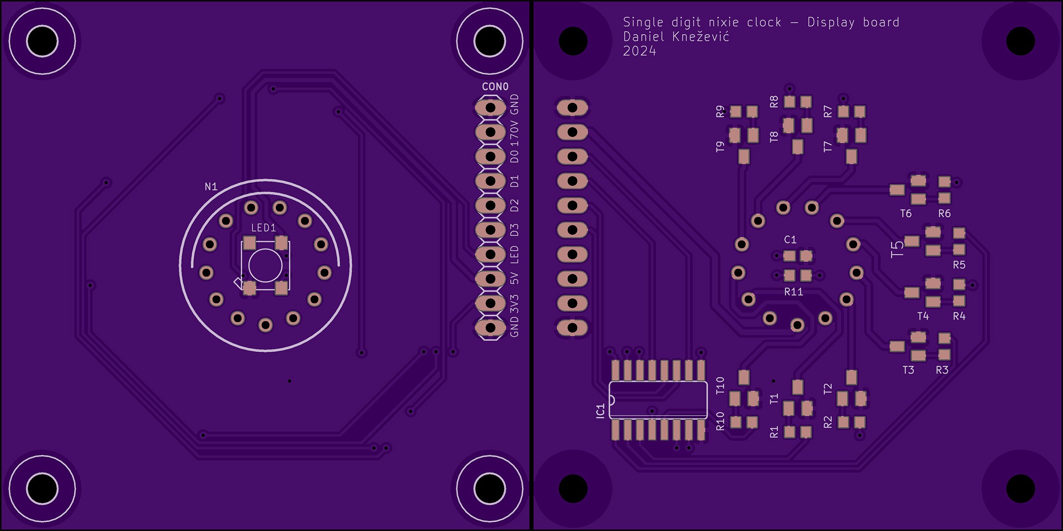
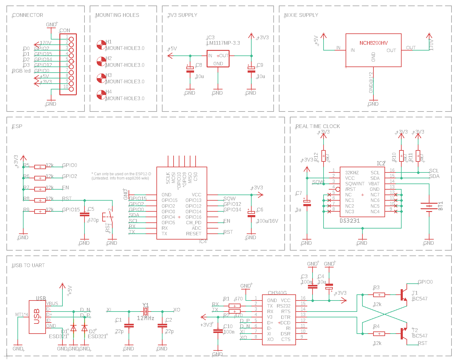 PCB
PCB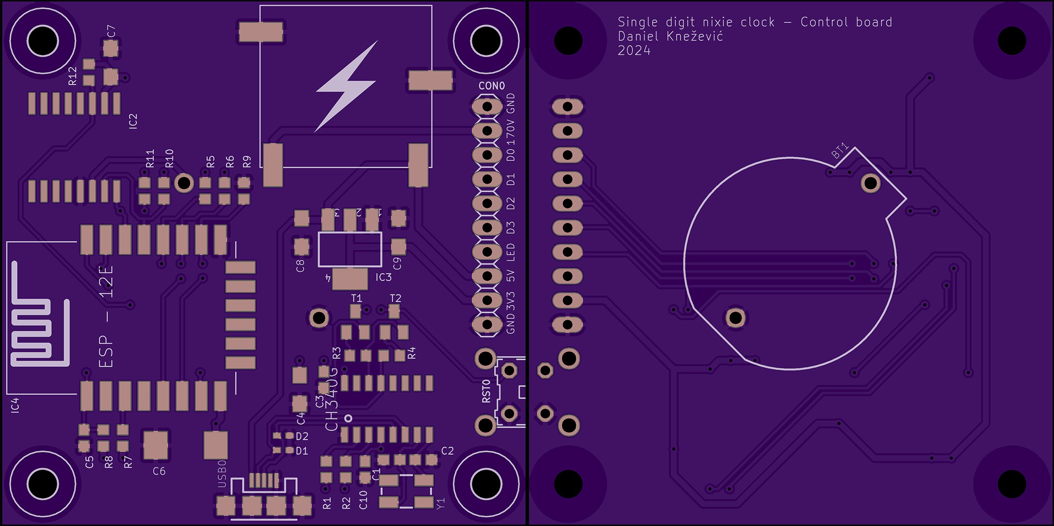

 Tobias Rathje
 Tim S
Tim S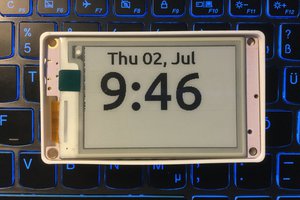
 Martin Fasani
 Jonathas Barbosa
Ah yes, the teltale upside down 2 for the 5 in some Soviet tubes. Fun project.