0%
0%
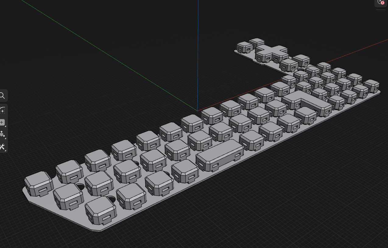
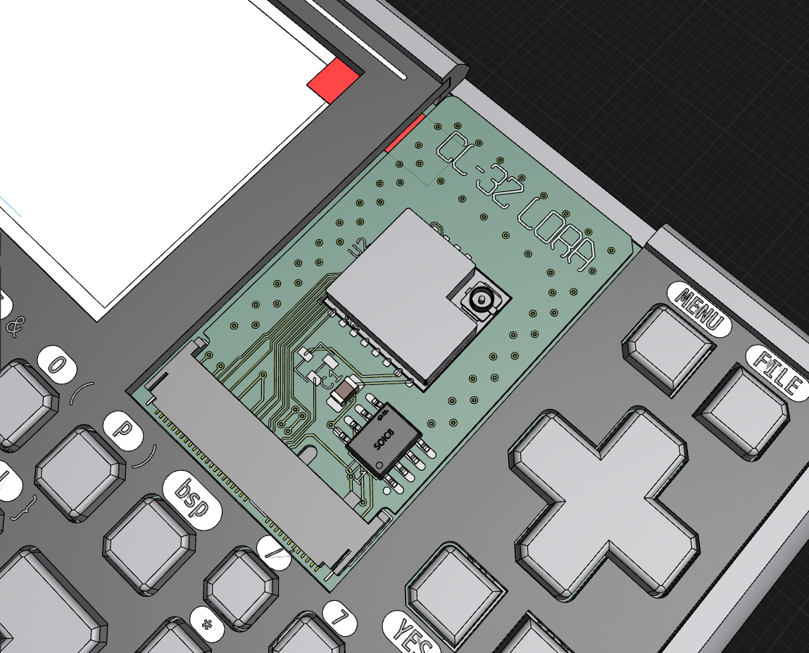
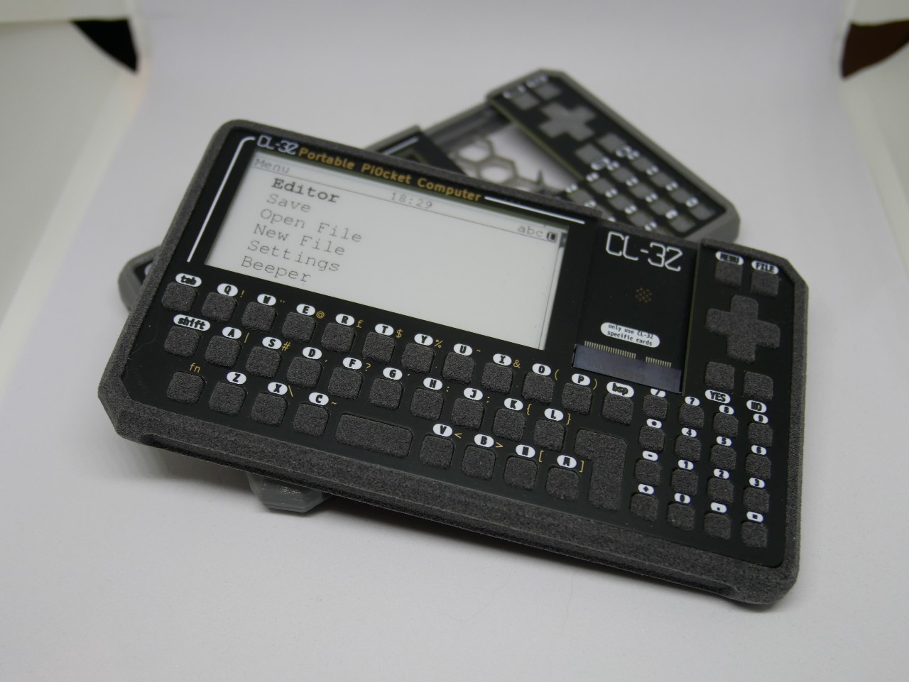
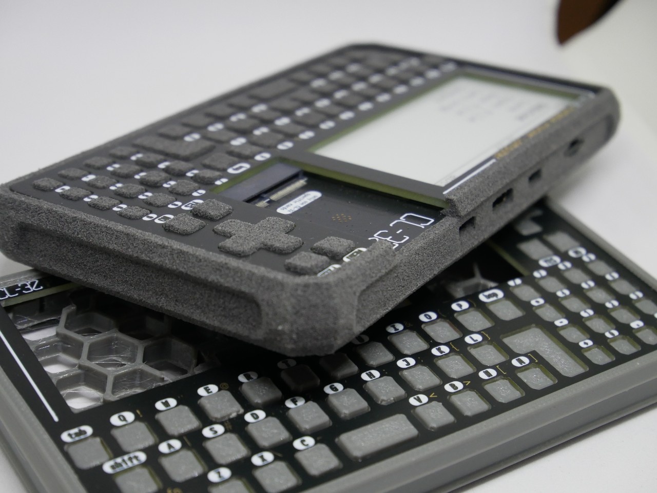
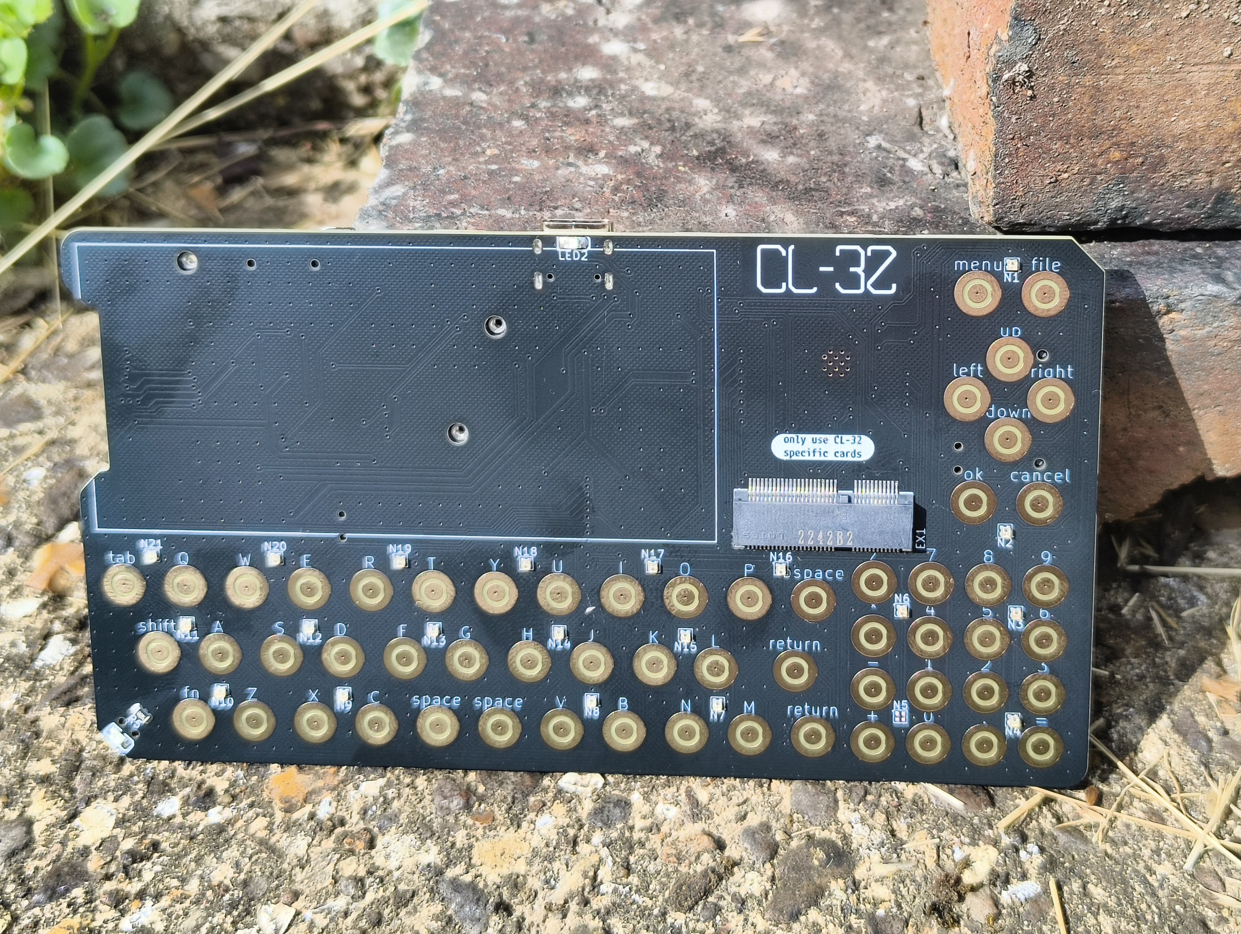
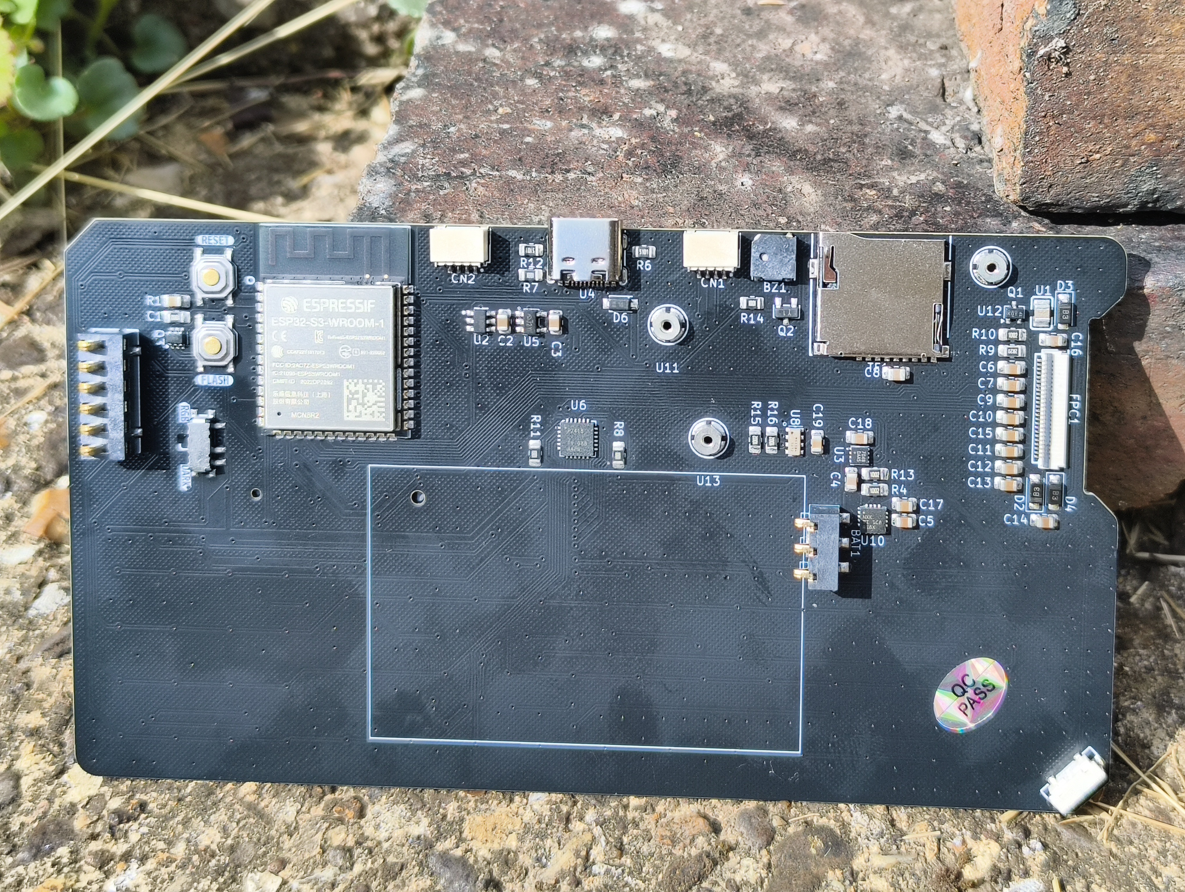
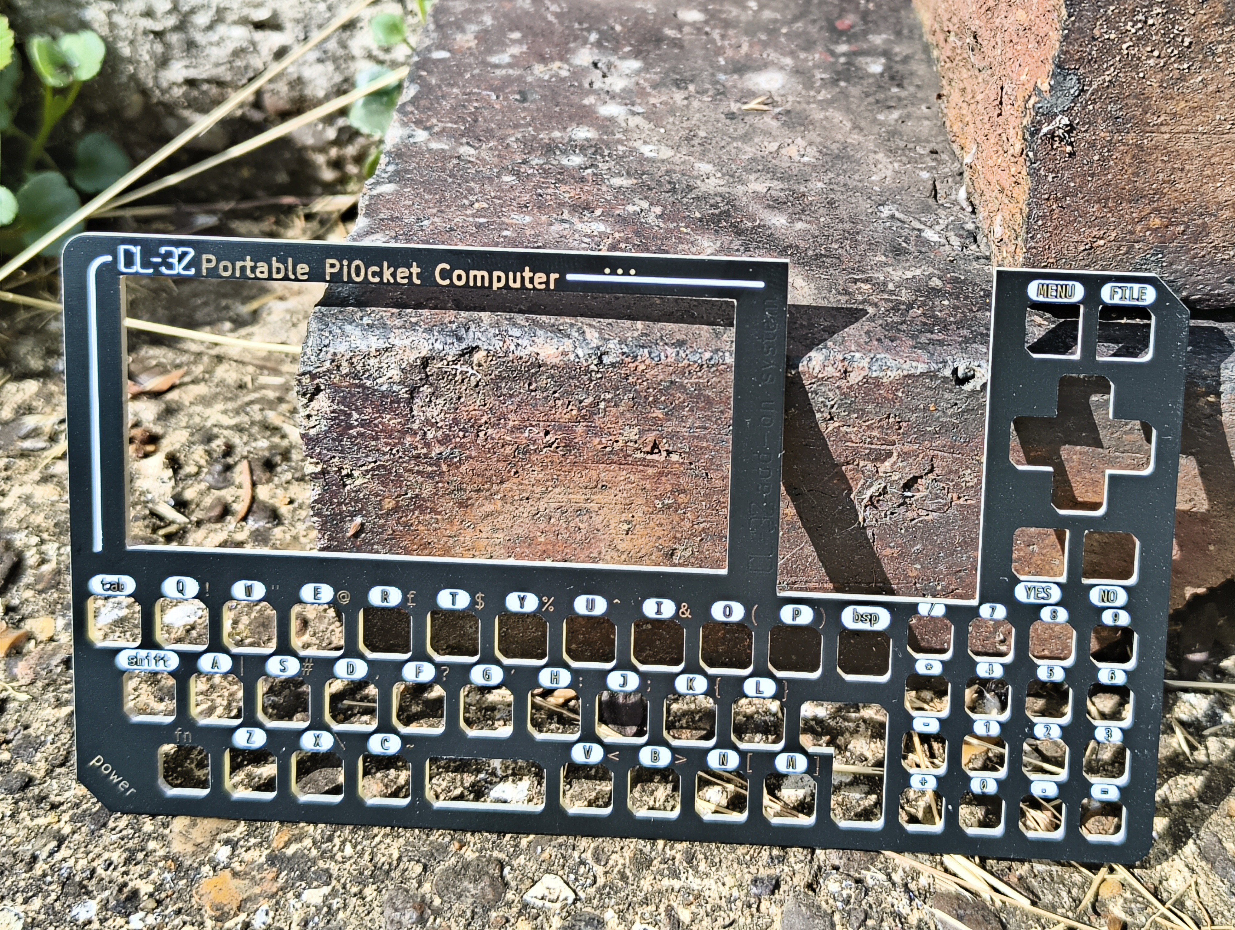
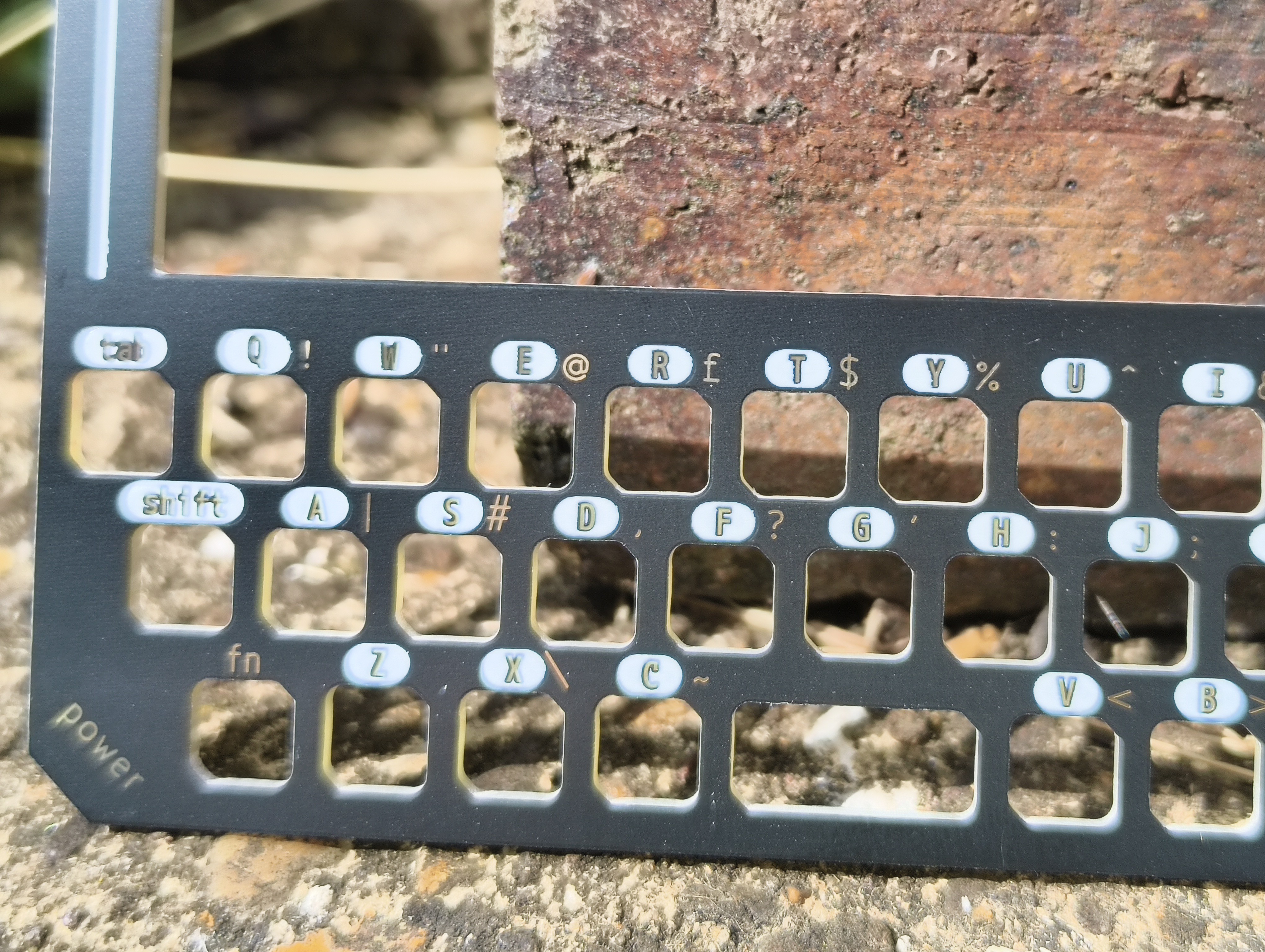
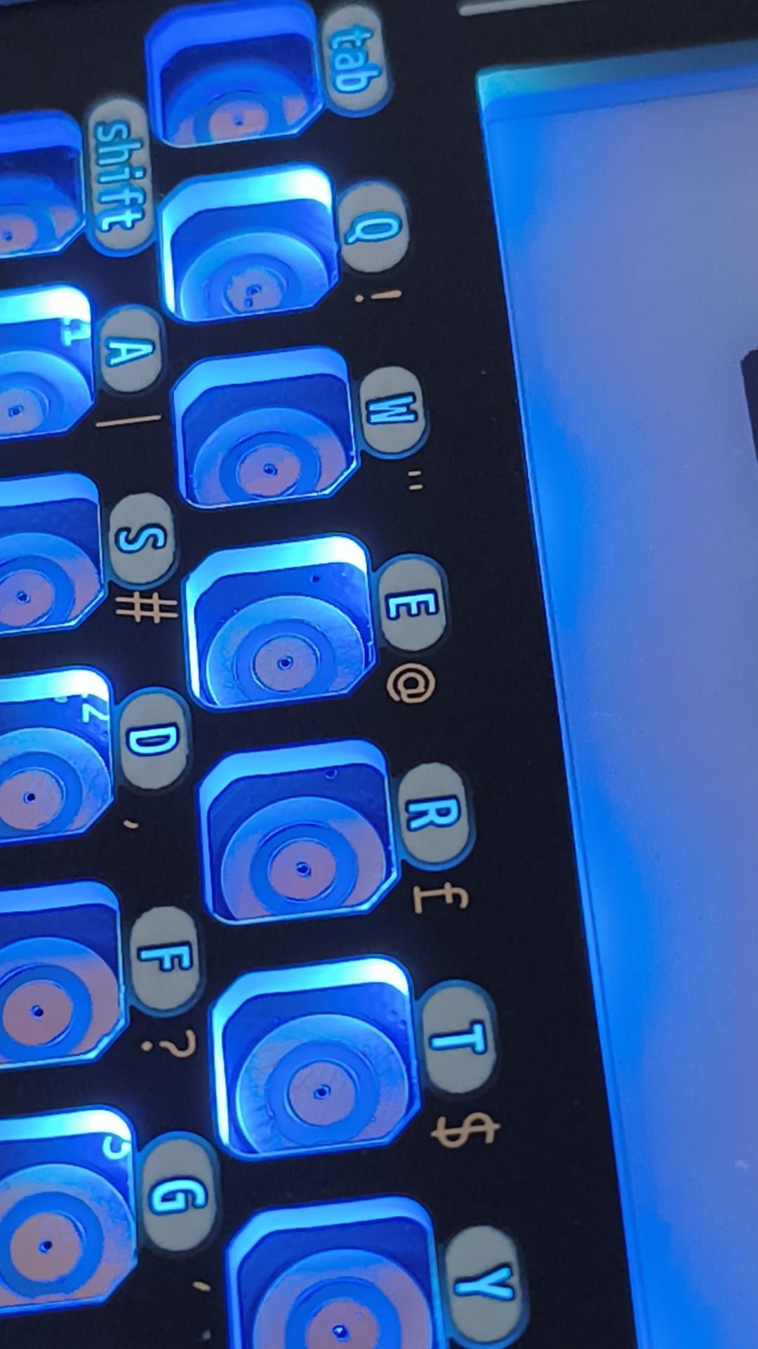
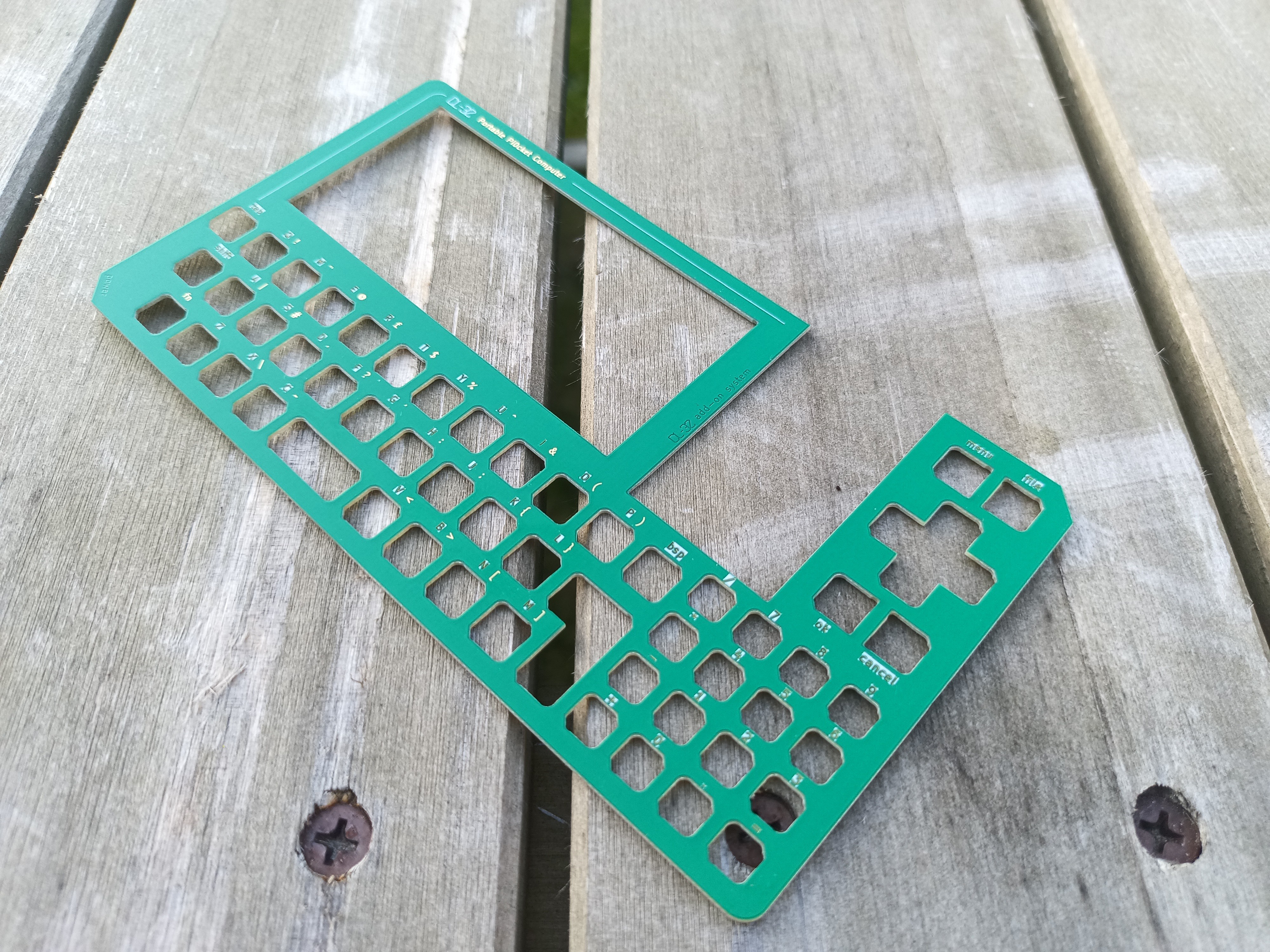
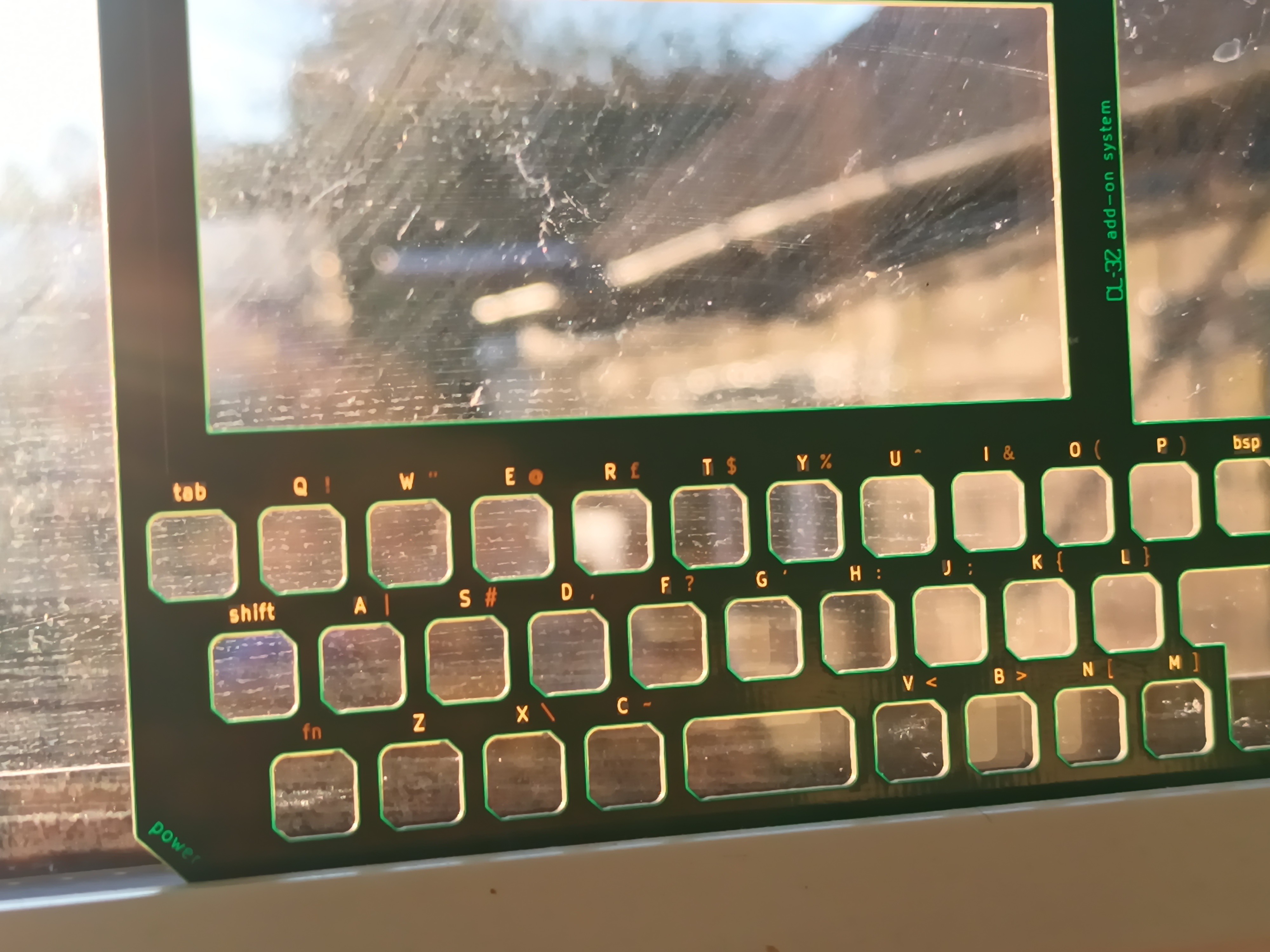
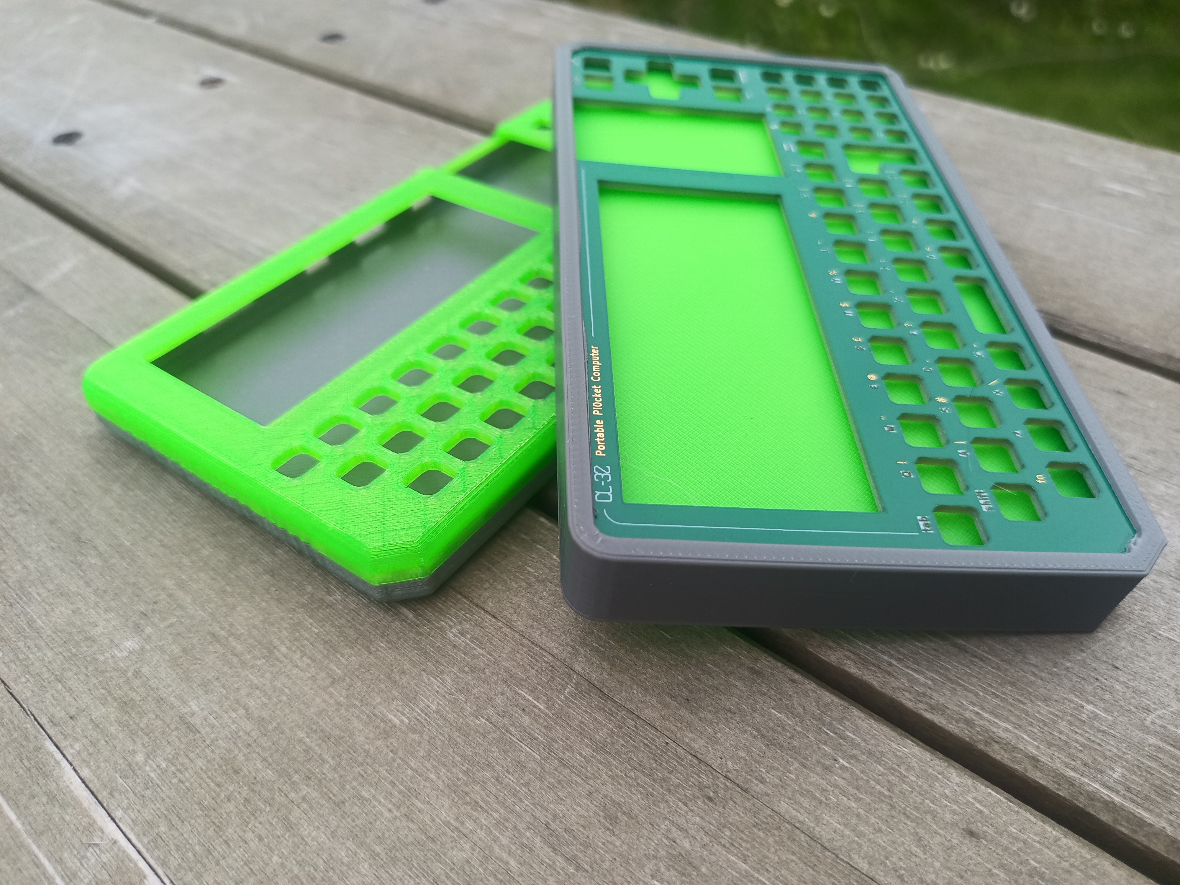
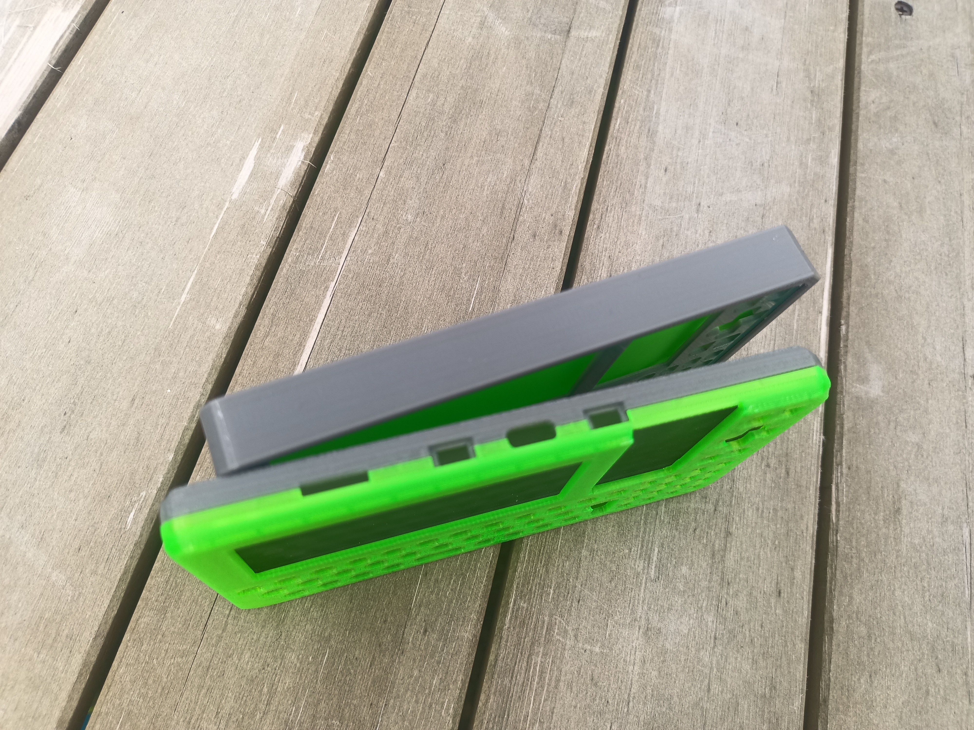
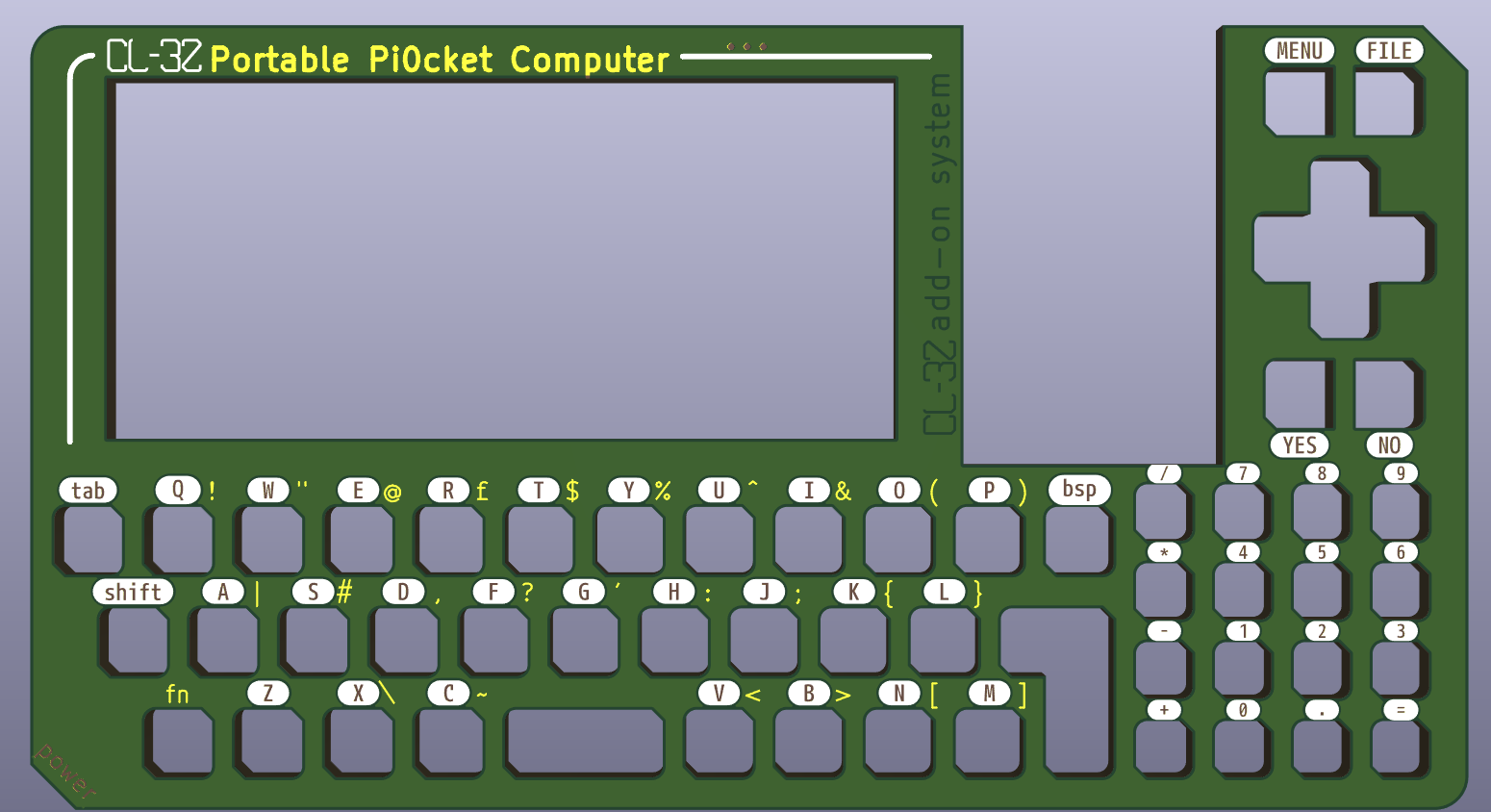
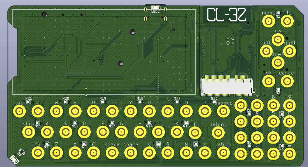
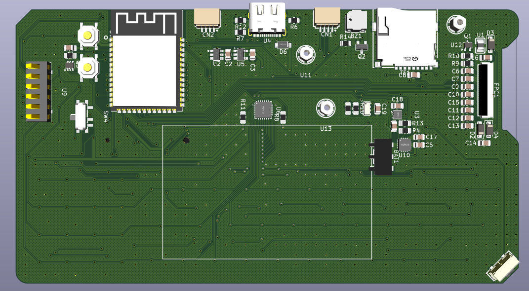
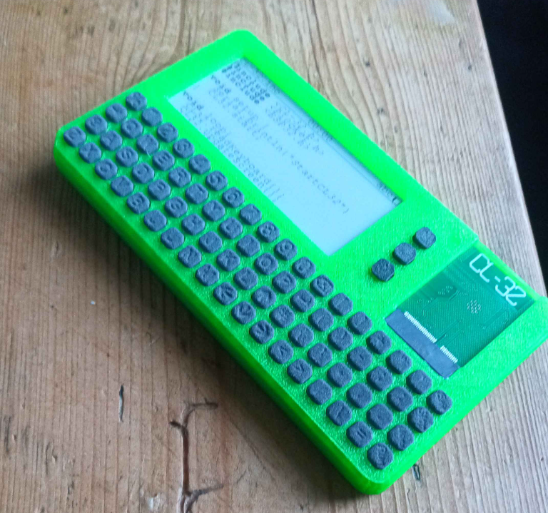
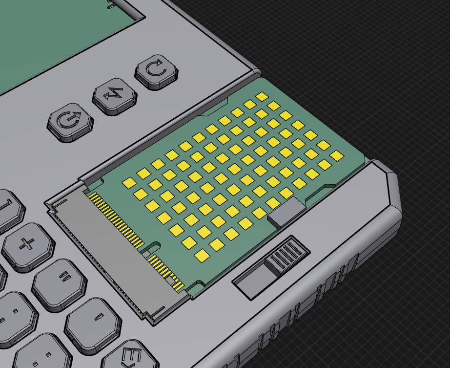
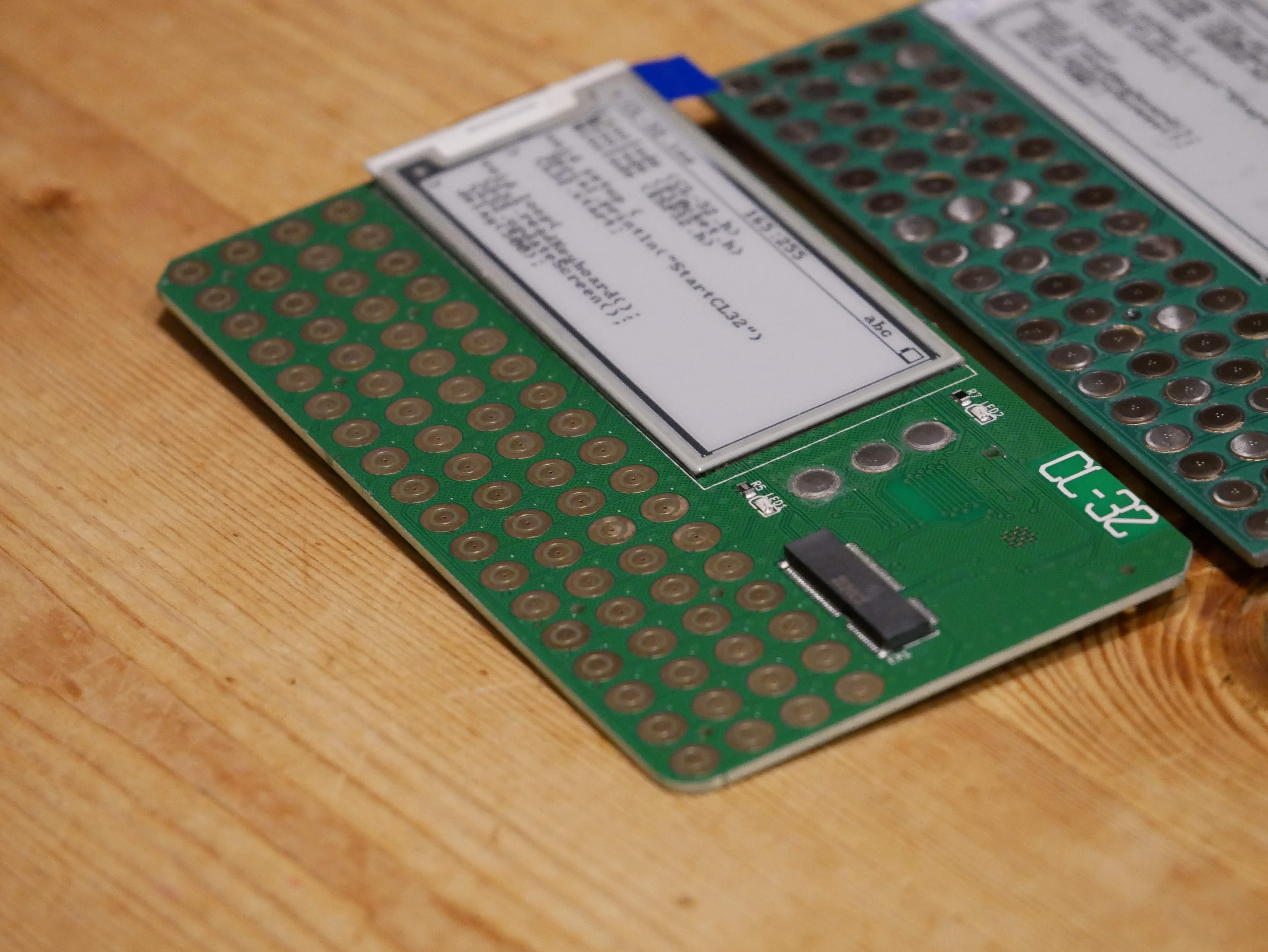
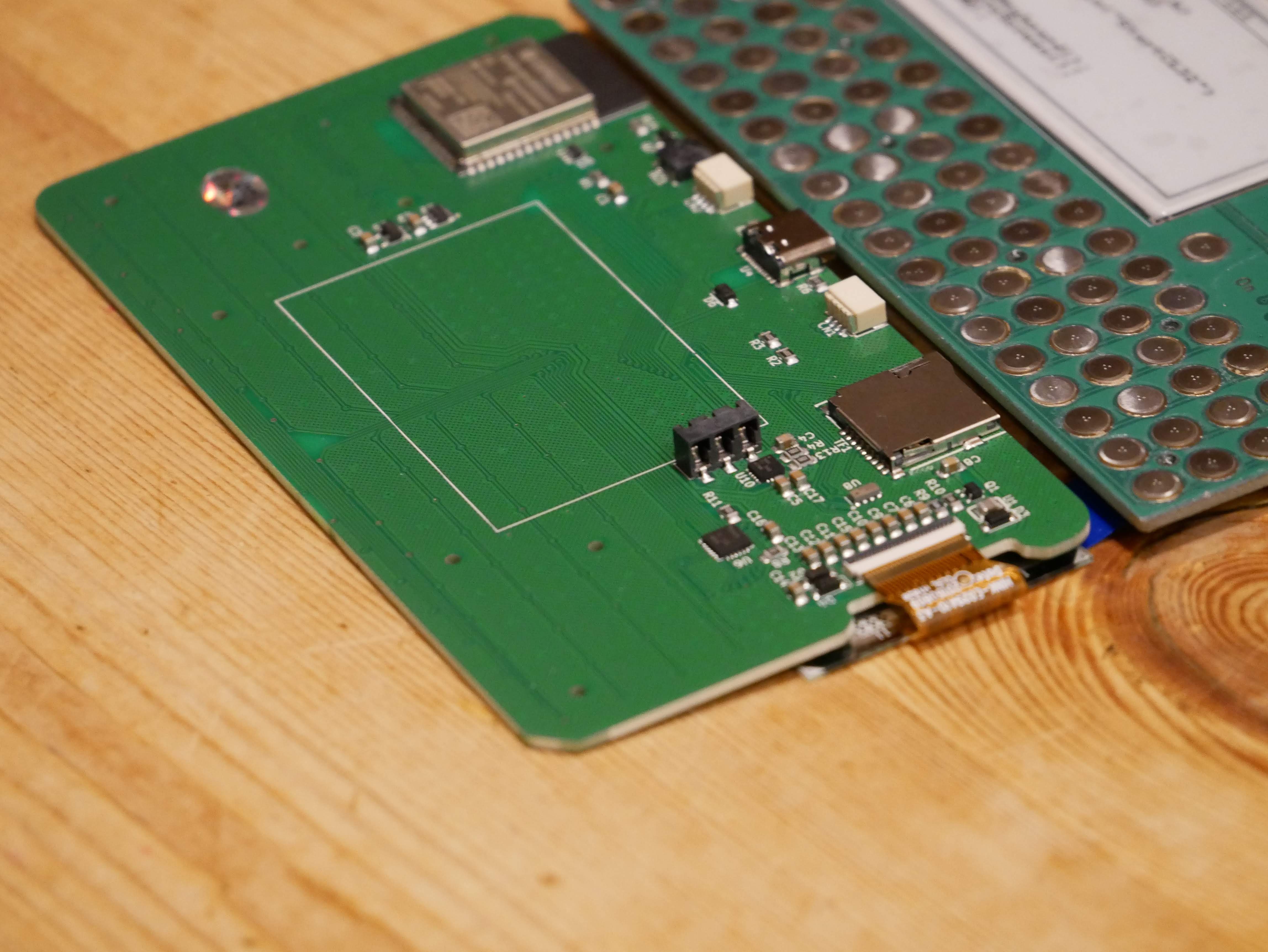
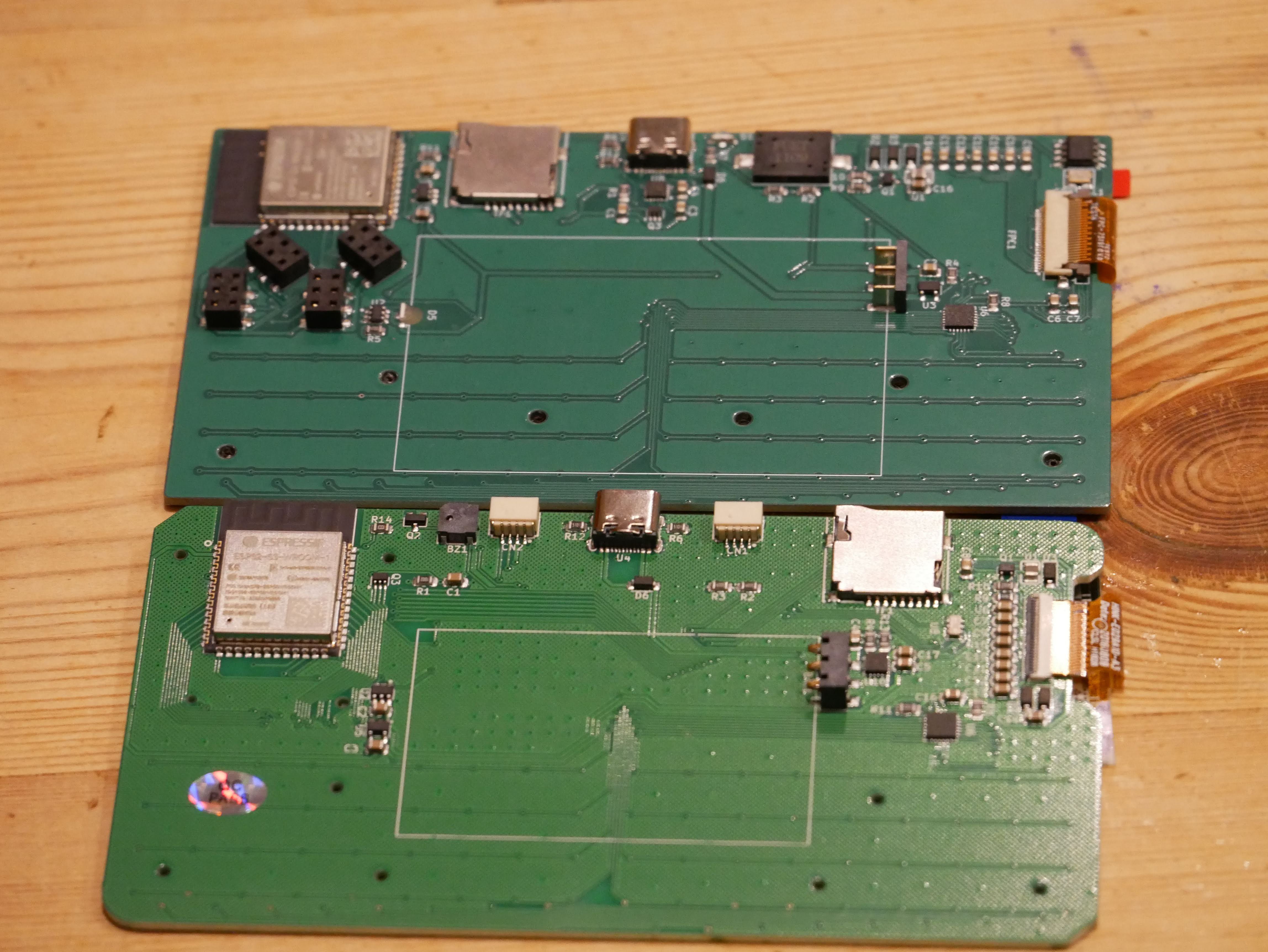
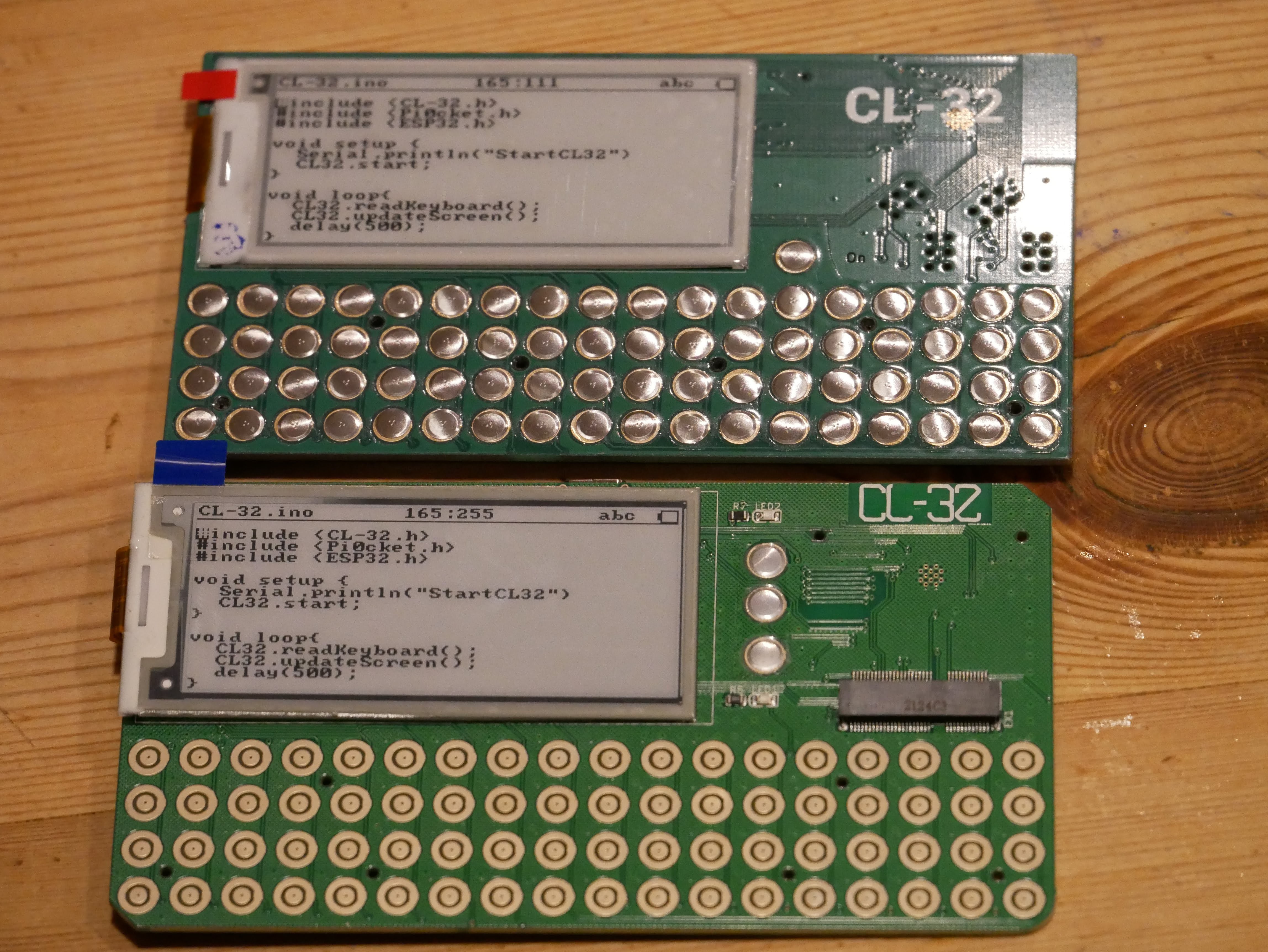
CL-32
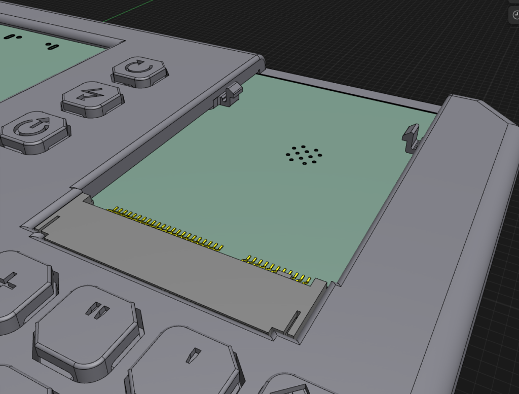
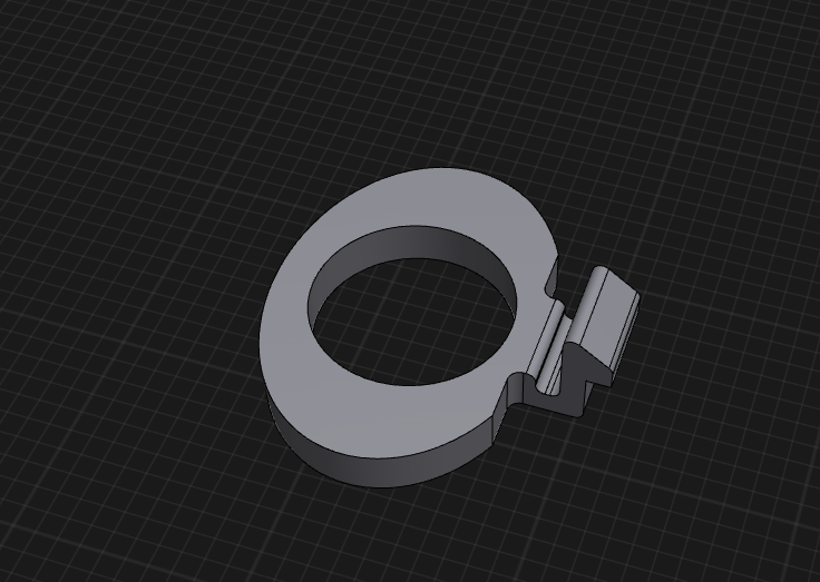
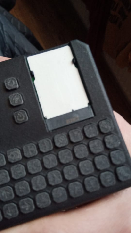
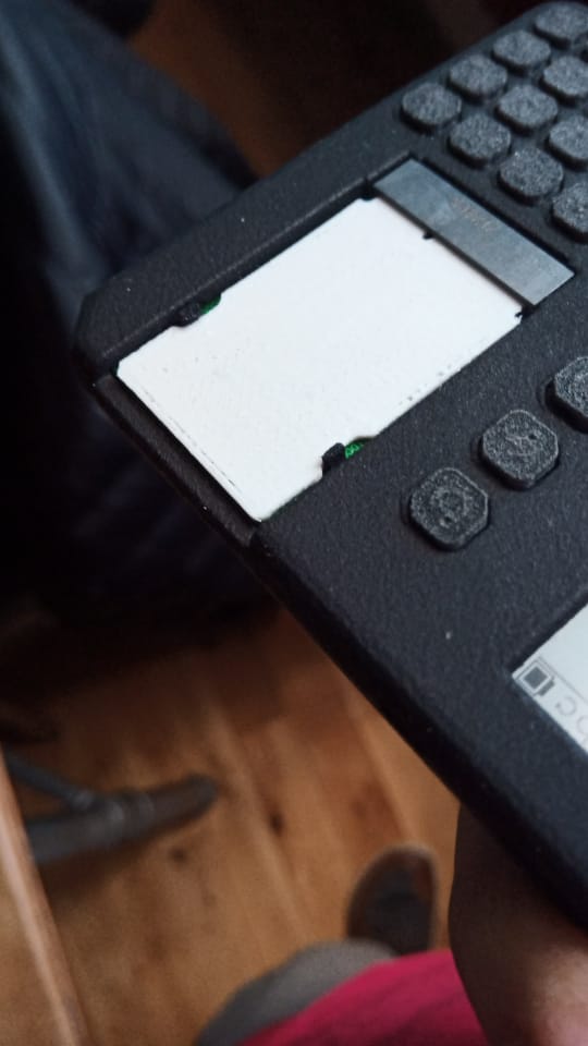
A mobile dev terminal, hacker device, anything you like!!
 moosepr
Become a Hackaday.io member
Already have an account? Log in.
Just one more thing
To make the experience fit your profile, pick a username and tell us what interests you.
Pick an awesome username
hackaday.io/
Your profile's URL: hackaday.io/username. Max 25 alphanumeric characters.
Pick a few interests
Projects that share your interests
People that share your interests


 Xasin
Xasin
 Jean Simonet
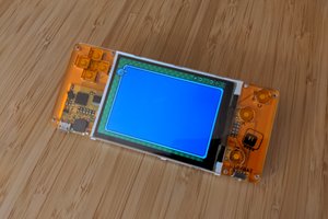
 deʃhipu
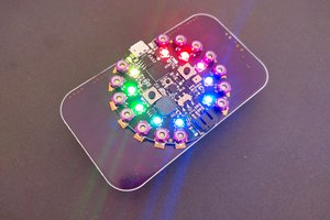
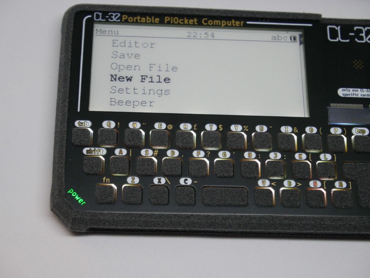
Hey! I dig this project. How is e-ink working out for you? I love e-ink as a technology, but it's difficult for anything that needs to refresh quickly (like typing).